Conveying device for conveying workpieces
- Summary
- Abstract
- Description
- Claims
- Application Information
AI Technical Summary
Benefits of technology
Problems solved by technology
Method used
Image

Examples
Embodiment Construction
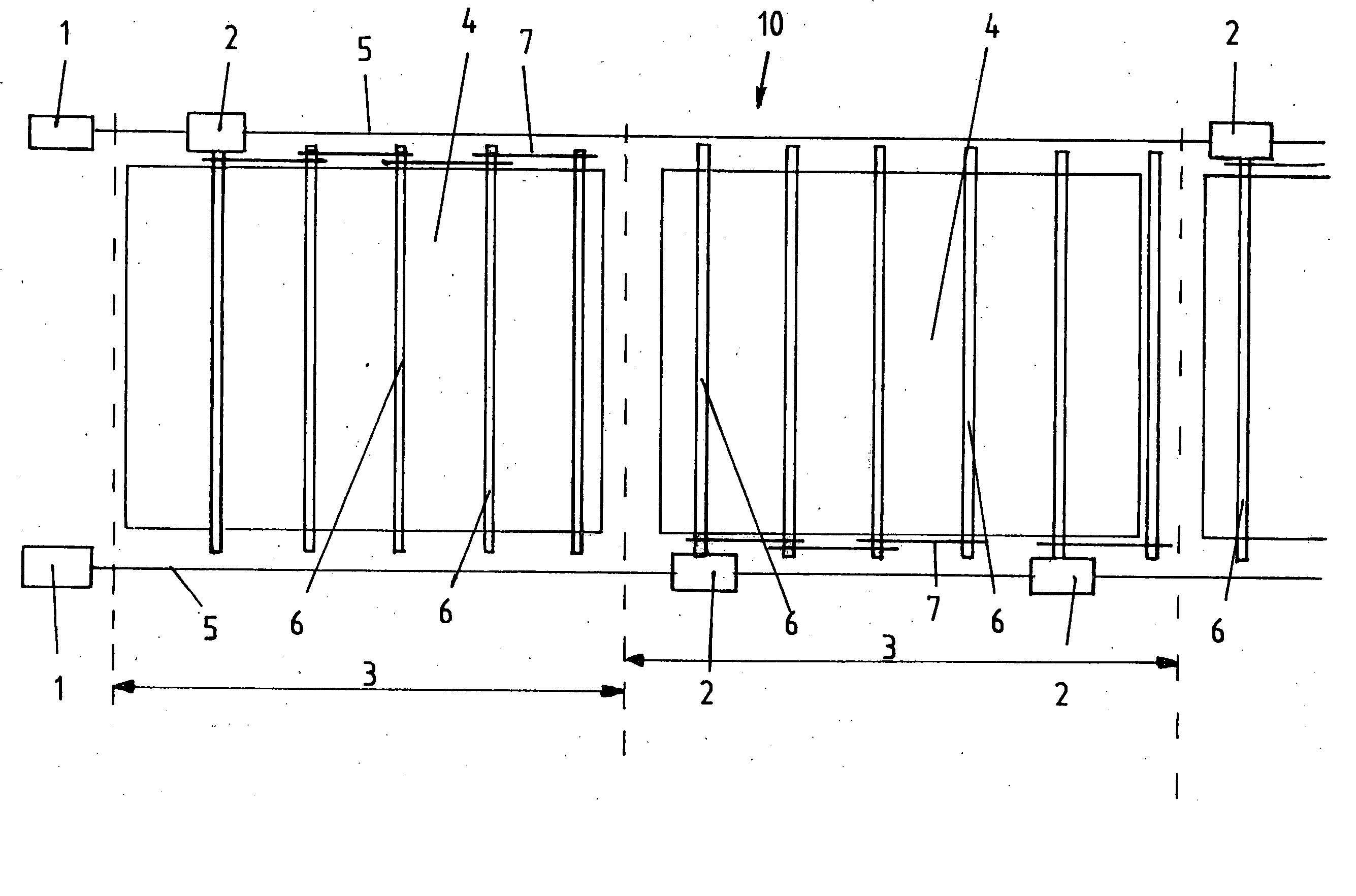
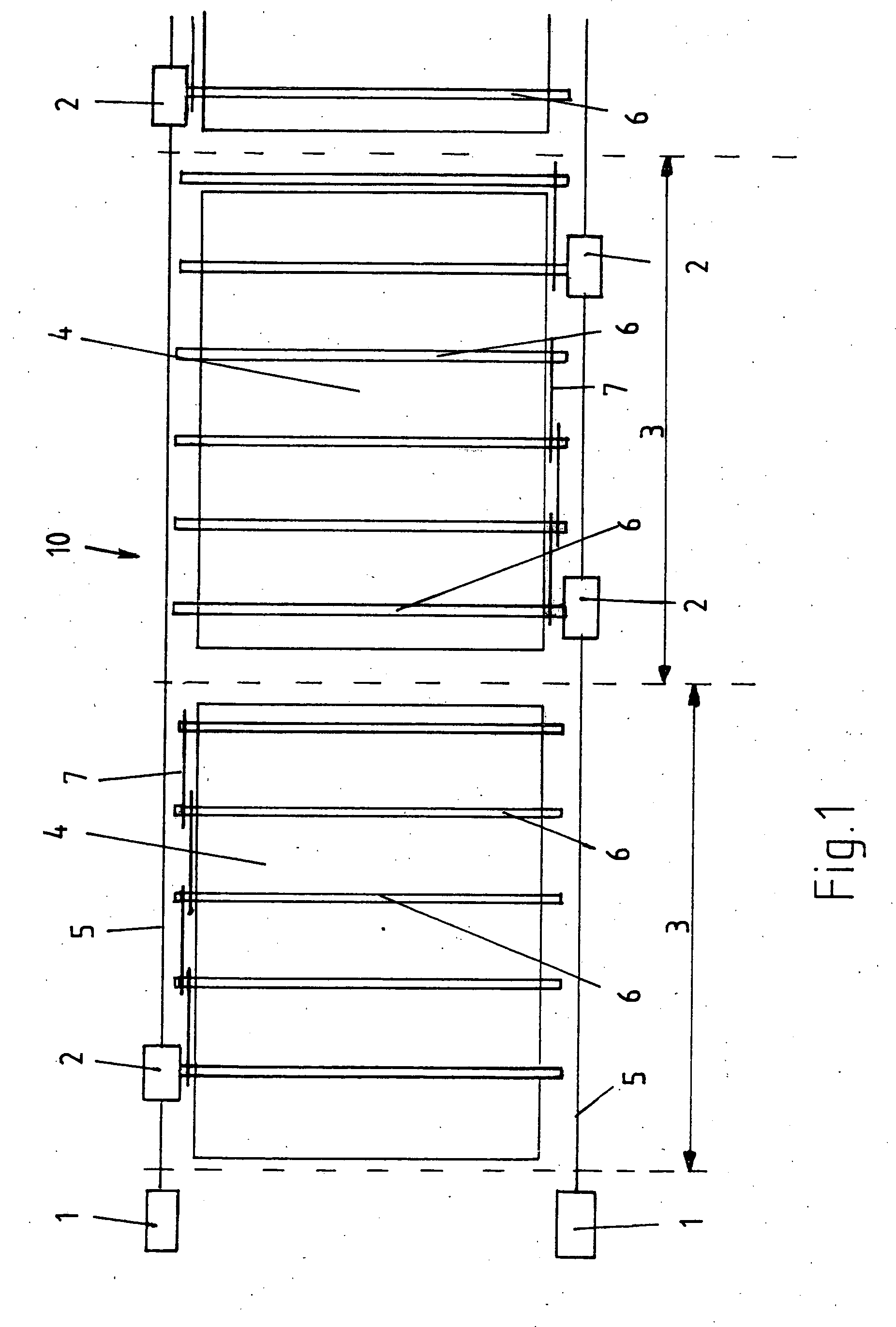
[0031]FIG. 1 shows a top view of a driving line 10 designed as a roller conveyor of the conveying device according to the invention. On both sides of the driving line central drives 1 are arranged which drive via a drive shaft 5 the respective sections 3 of the driving line 10 designed as a roller conveyor. Reference number 2 indicates here the couplings which are arranged alternating along the driving line 10 in the embodiment according to FIG. 2. Reference number 3 indicates here the sections of the roller conveyor which can be controlled section by section by the central drive 1 via the coupling 2. The sections 3 are only shown schematically with dashed lines. On the rollers 6 of the roller conveyor here the workpieces 4 are positioned. The workpieces 4 can also be arranged on pallets when this seems useful according to the size of the respective workpiece. The individual rollers 6 of the roller conveyor are connected to each other via chain drives 7. Along the driving line here ...
PUM
 Abstract
Description
Claims
Application Information
 - Generate Ideas
- Intellectual Property
- Life Sciences
- Materials
- Tech Scout
- Unparalleled Data Quality
- Higher Quality Content
- 60% Fewer Hallucinations
Browse by: Latest US Patents, China's latest patents, Technical Efficacy Thesaurus, Application Domain, Technology Topic, Popular Technical Reports.
© 2025 PatSnap. All rights reserved.Legal|Privacy policy|Modern Slavery Act Transparency Statement|Sitemap|About US| Contact US: help@patsnap.com