
Portable foot rest with extendible pivotal legs

a technology of pivotal legs and foot rests, which is applied in the field of portable foot rests, can solve the problems of excessive force being put on one's thighs, people with short legs are also often in need of foot rests, etc., and achieve the effect of facilitating manual transportation of foot rests and reducing or eliminating sliding of foot rests

Inactive Publication Date: 2006-06-27
PUSSELL ROGER L
View PDF8 Cites 20 Cited by
  • Summary
  • Abstract
  • Description
  • Claims
  • Application Information

AI Technical Summary

Benefits of technology

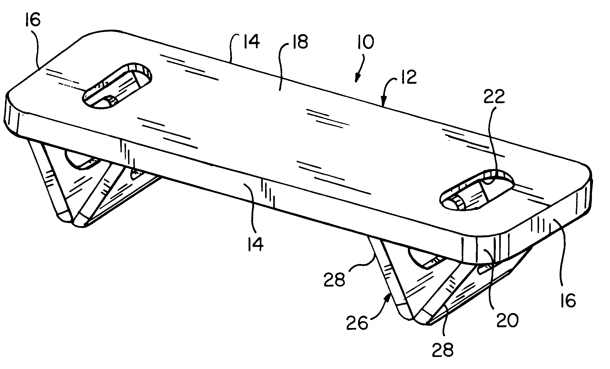
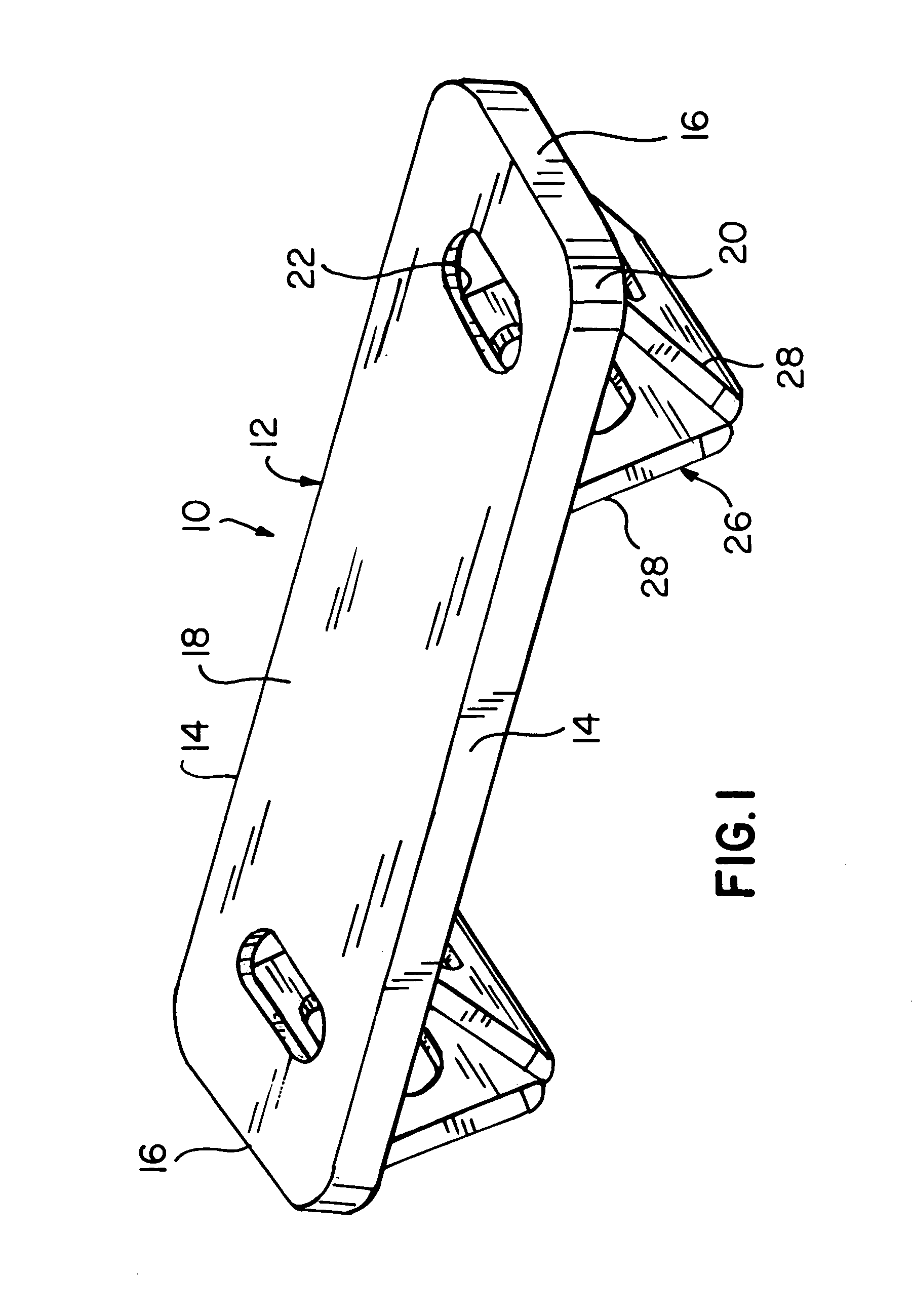
[0012]The present invention is directed to a versatile and portable foot rest that functions as a stable foot rest resting on a supporting surface, i.e. floor, while further offering the user the opportunity to exercise one's feet through the positioning of a pair of pivotal legs inwardly from the ends. By this arrangement, one can exercise the ankles with a teeter-totter motion about the respective pivot points of the legs. The portable and pivotal foot rest of this invention comprises a generally rectangular housing with a planar upper surface, a pair of elongated side edges, and a pair of shorter ends joined with said side edges. The housing is further characterized by a downwardly extending peripheral side wall for receiving a pair of recessible, pivotal legs in an inoperative and transportable mode. In the operative or foot supporting mode, the legs may be pivoted about a mid-portion thereof and conveniently and releasably locked, where the respective legs form a V-configured leg. The mid-portion further features a flexible, elastomeric covering to minimize or eliminate sliding of the foot rest. By positioning the mid-portions of the respective legs inwardly from the shorter ends, preferably about 16 to 18% from the respective shorter ends, the user thereof can easily pivot about the mid-portions, i.e. in a teeter-totter motion, to effect movement and thus exercising of the user's ankles. To facilitate manual transporting of the foot rest hereof, at least one transverse slot may be provided to accommodate the user's fingers.

Problems solved by technology

People with short legs are also often in need of a foot rest when seated in automobiles, airplanes and other types of chairs because their feet may not reach the floor, and excessive forces are consequently put on one's thighs.

Method used


Image

  • Portable foot rest with extendible pivotal legs
  • Portable foot rest with extendible pivotal legs
  • Portable foot rest with extendible pivotal legs

Examples


Embodiment Construction

[0025]This invention relates to a portable, stable foot rest that is versatile in its ability to offer the user a stable foot rest, and an ankle exercising device while positioned on a supporting surface, such as a floor. The invention will now be described with regard to the several Figures, where like reference numerals represent like components or features throughout the various views.

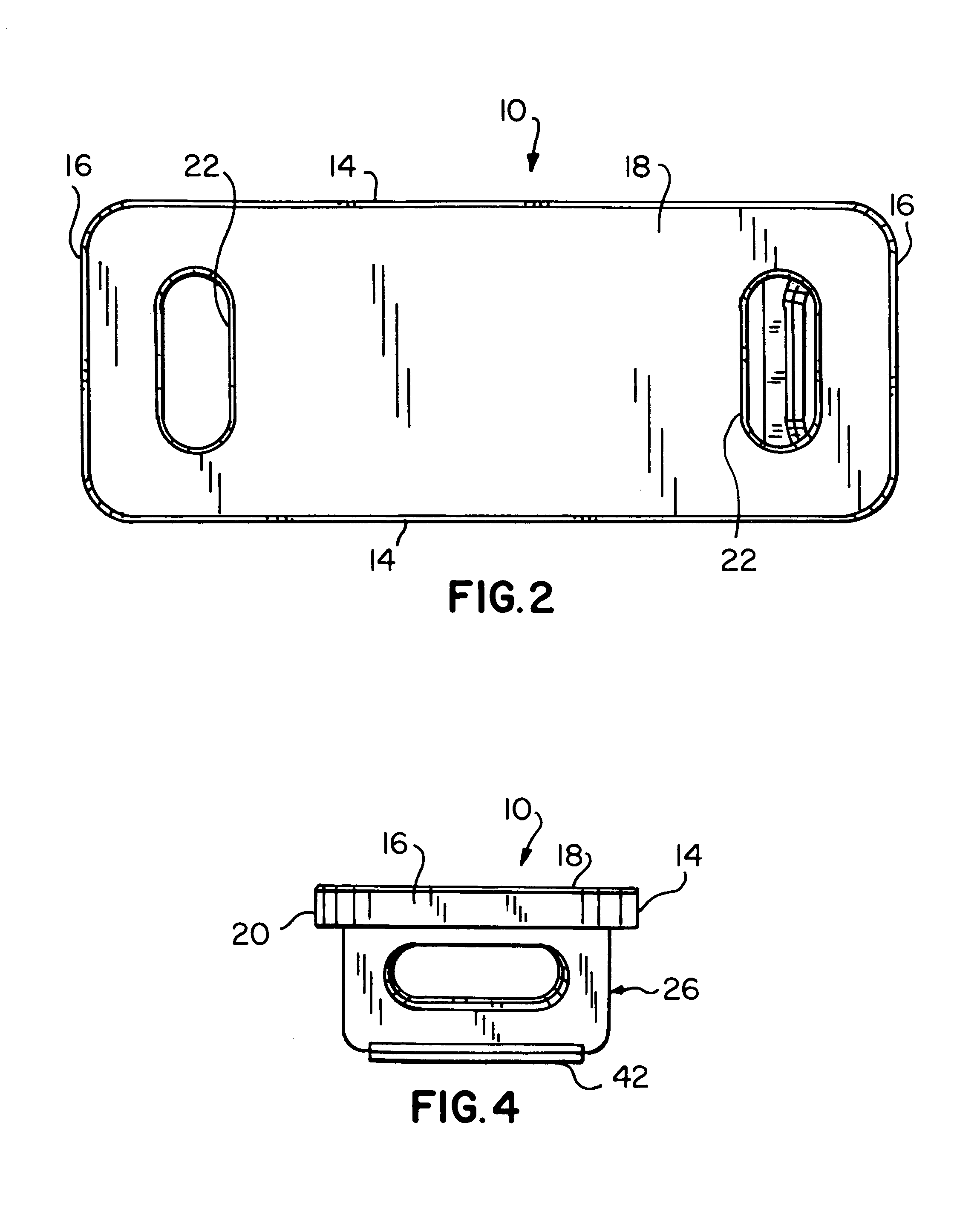
[0026]Turning now to FIGS. 1 through 8, illustrating various views of the foot rest 10 of the invention, preferably fabricated of plastic, such as PVC, as known in the art, the foot rest comprises a generally rectangular housing 12 formed by a pair of parallel sides 14, a pair of ends 16 extending between said sides 14, a planar upper, foot supporting surface 18, and a downwardly extending, continuous, peripheral wall 20. Further, the housing opening to the foot supporting surface 18 may include one or more through openings 22 in proximity to the ends 16 for use in hand gripping and transporting the...


PUM


Abstract

A portable and stabilized foot rest for positioning on a supporting surface, such as a floor, or the like. The foot rest comprises a generally, rectangularly shaped housing mounting a pair of V-configured legs recessible within the housing in a storage or transporting mode, and extendible for use in a foot supporting mode. Plural releasable locking mechanisms are provided to secure the foot rest in the respective modes.

Description

FIELD OF THE INVENTION[0001]This invention is directed to the field of portable foot rests, more particularly to a portable foot rest having two-piece extendible, pivotal legs that may be locked to prevent premature collapsing thereof.BACKGROUND OF THE INVENTION[0002]The present invention relates to an improved foot rest that can be readily transported by the user, where the foot rest includes a pair of balanced pivotal legs to provide a stationary foot rest and a teeter totter-like foot rest to help in exercising the user's ankles, especially for use by height challenged people.[0003]It is a well known medical phenomenon that physical discomfort in the lower back of a seated person can often be relieved by elevating the feet on a foot rest, footstool or ottoman. Further, the serious complications from dependent edema from prolonged sitting may be reduced by elevating the feet on a foot rest of some sort. People with short legs are also often in need of a foot rest when seated in au...

Claims


Application Information

Patent Timeline
IPC IPC(8): A47C16/00
CPCA47C16/025A47C9/002
Inventor RUSSELL, ROGER L.LAPP, JR., JOHN K.RUTKOWSKI, RAYMOND R.
Owner PUSSELL ROGER L
Learn More