Fabricated mold plate supporting device of shaped concrete tunnel body

A technology of formwork support and concrete, which is applied in the direction of formwork/formwork/work frame, connectors of formwork/formwork/work frame, and preparation of building components on site, which can solve the problems of high formwork rigidity, damage to the inner wall surface of structures To solve the problems of large cross-section changes of structures, etc., to achieve the effects of reducing the deformation of structures and components, clear and direct force transmission paths, and the overall rigidity of large spaces

Inactive Publication Date: 2019-02-15
SOUTHWEAT UNIV OF SCI & TECH
View PDF9 Cites 2 Cited by
  • Summary
  • Abstract
  • Description
  • Claims
  • Application Information

AI Technical Summary

Problems solved by technology

Due to the large span and height, the weight of concrete slabs and beams is very large. The traditional support method is used for construction, and the steel support is heavy, which will make it impossible to use small equipment or manual installation and removal, and the installation accuracy is extremely high.
[0003] Although segmental construction can be adopted, the cave is in a closed state, and the feasibility of lifting the internal support system by machinery is extremely low, and the installation accuracy is not easy to control. Large changes, various sizes of supporting rods and formwork, extremely low reuse rate, high formwork rigidity required, and high cost
After the concrete reaches its age, the internal support system is removed by mechanical dragging and heavy tonnage support, which is likely to cause surface damage to the inner wall of the structure
[0004] Inven

Method used


Image

  • Fabricated mold plate supporting device of shaped concrete tunnel body
  • Fabricated mold plate supporting device of shaped concrete tunnel body
  • Fabricated mold plate supporting device of shaped concrete tunnel body

Examples


Embodiment Construction

[0036] The specific embodiments of the present invention are described below so that those skilled in the art can understand the present invention, but it should be clear that the present invention is not limited to the scope of the specific embodiments. For those of ordinary skill in the art, as long as various changes Within the spirit and scope of the present invention defined and determined by the appended claims, these changes are obvious, and all inventions and creations using the concept of the present invention are included in the protection list.

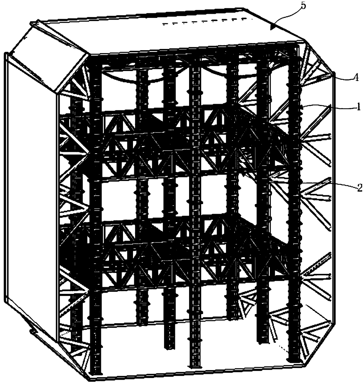
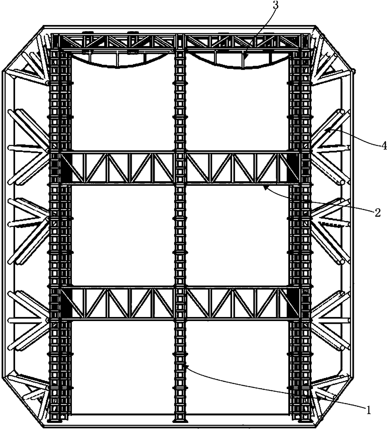
[0037] The structure of the formwork 5 that needs to be supported by the special-shaped concrete hole assembled formwork 5 supporting device of this program can be found in figure 1 with figure 2 The outermost layer of the middle is similar to the structure of the progressively shrinking octagon except the bottom surface, such as Figure 9 As shown, the formwork 5 includes a steel inner formwork 51 and a wooden outer form...


PUM


Abstract

The invention discloses a fabricated mold plate supporting device of a shaped concrete tunnel body. The fabricated mold plate supporting device comprises a plurality of lattice columns, one or more layers of plane truss beams are arranged on a square columnar support composed of all lattice columns in the height direction, and the plane truss beams include a plurality of transverse truss beams fixedly connected between two adjacent lattice columns and a plurality of longitudinal truss beams connected between two adjacent and parallel transverse truss beams; tension chord truss beams are fixedly installed between the lattice columns at the edge of the top end of the columnar support, the plane truss beams are installed at the top ends of the lattice columns located in the space enclosed byall tension chord truss beams, and the plane truss beams at the top ends of the lattice columns and the tension chord truss beams are fixedly connected through the transverse truss beams and the longitudinal truss beams; and a plurality of supporting mechanisms for supporting the side faces of mold plates are arranged on the two lines of the lattice columns which are parallel to the longitudinal truss beams and located at the outermost layer in the height direction.

Description

technical field [0001] The invention relates to the technical field of construction engineering, in particular to an assembled formwork support device for a special-shaped concrete cavity. Background technique [0002] In the construction of tunnel concrete engineering, structures such as subways, pipe galleries, and wind tunnel laboratories have large cross-sectional changes, and the constructed concrete tunnels have a large cross-sectional size, with a horizontal net width of more than 20 meters and a height of more than 20 meters. The entire length of the wind tunnel shrinks gradually, and each surface shrinks in a trapezoidal state along the longitudinal direction, belonging to a special-shaped concrete structure. Due to the large span and height, the weight of concrete slabs and beams is very large. The traditional support method is used for construction, and the steel support is heavy. It will make it impossible to use small equipment or manual installation and removal...

Claims


Application Information

Patent Timeline
IPC IPC(8): E04G11/02E04G11/52E04G17/14
CPCE04G11/02E04G11/52E04G17/14
Inventor 古松褚云朋宋星宇侯鸿杰顾颖任松波孔超
Owner SOUTHWEAT UNIV OF SCI & TECH
Why Eureka
Try Eureka