Chin up bar assembly with sliding and swiveling handles

a technology of sliding and swiveling handles and chin up bars, which is applied in the direction of gymnastic exercise, therapy exercise, sport apparatus, etc., can solve the problems of difficult actuation or release, limited spacing between the handles,

Inactive Publication Date: 2006-06-27
CONNER ATHLETIC PRODS
View PDF13 Cites 67 Cited by
  • Summary
  • Abstract
  • Description
  • Claims
  • Application Information

AI Technical Summary

Benefits of technology

[0012]The chin up bar assembly of the present invention includes a cross bar and a pair of handles slidably mounted on the cross bar. The handles are pivotally mounted to the cross bar so as to be movable between locked and unlocked positions. In the unlocked position, the handles are slidable along the cross ba

Problems solved by technology

However, such pins are often difficult to actuate or release, and the spacing

Method used


Image

  • Chin up bar assembly with sliding and swiveling handles
  • Chin up bar assembly with sliding and swiveling handles
  • Chin up bar assembly with sliding and swiveling handles

Examples


Embodiment Construction

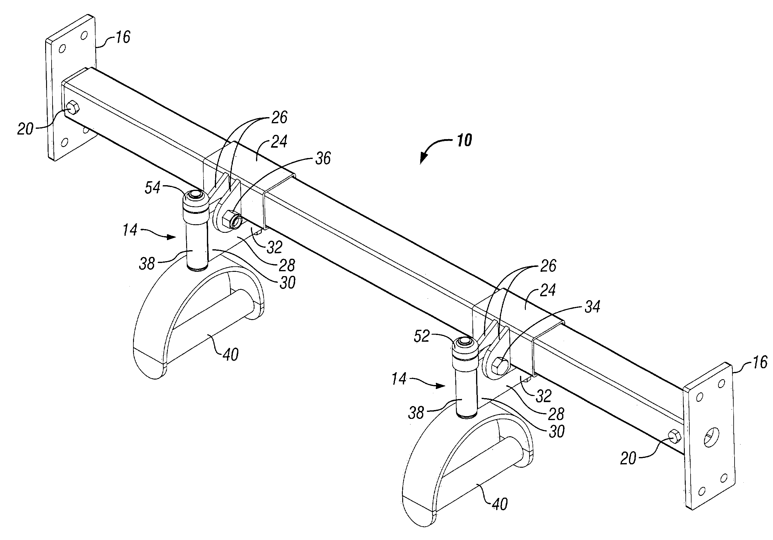
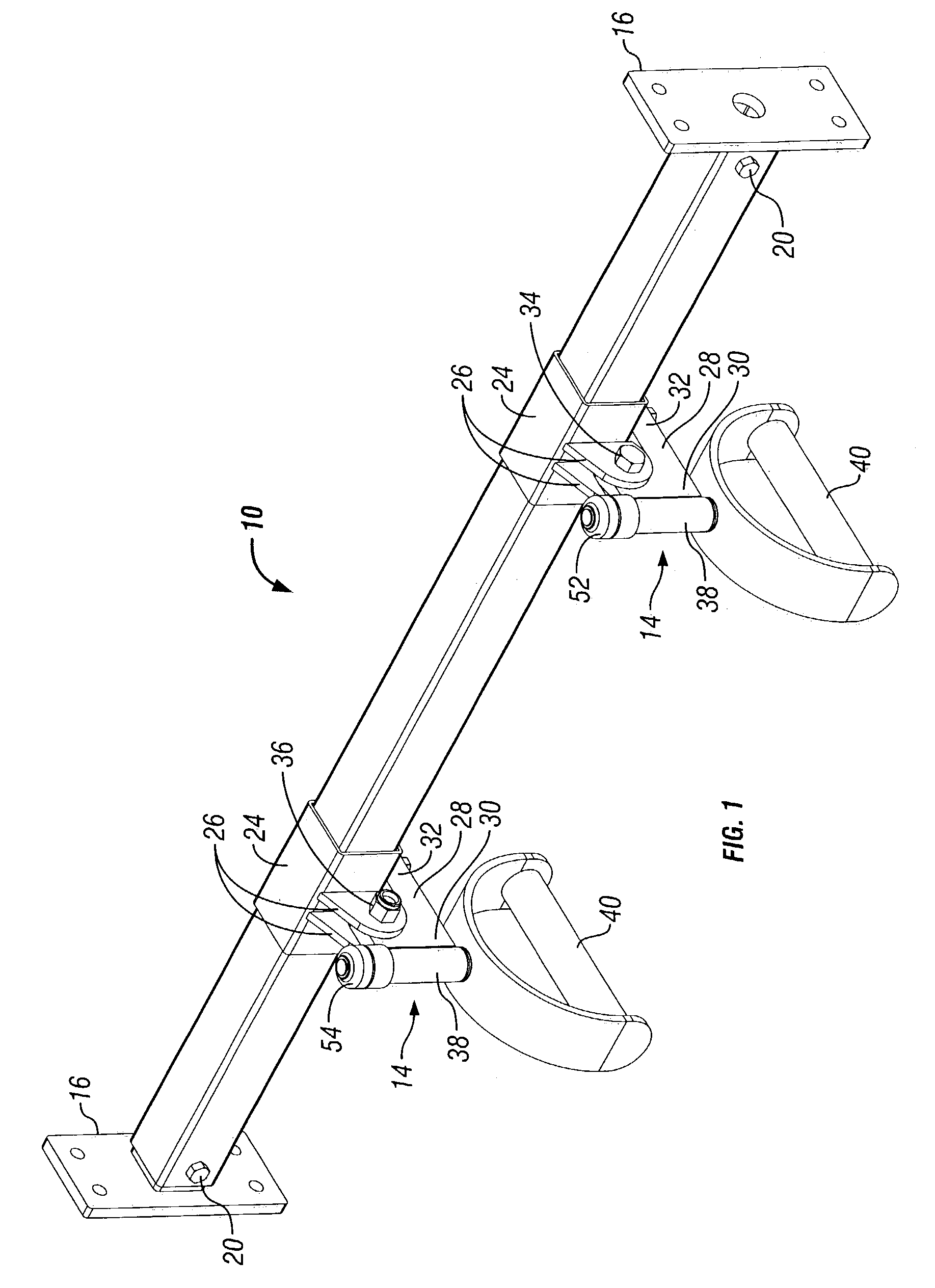
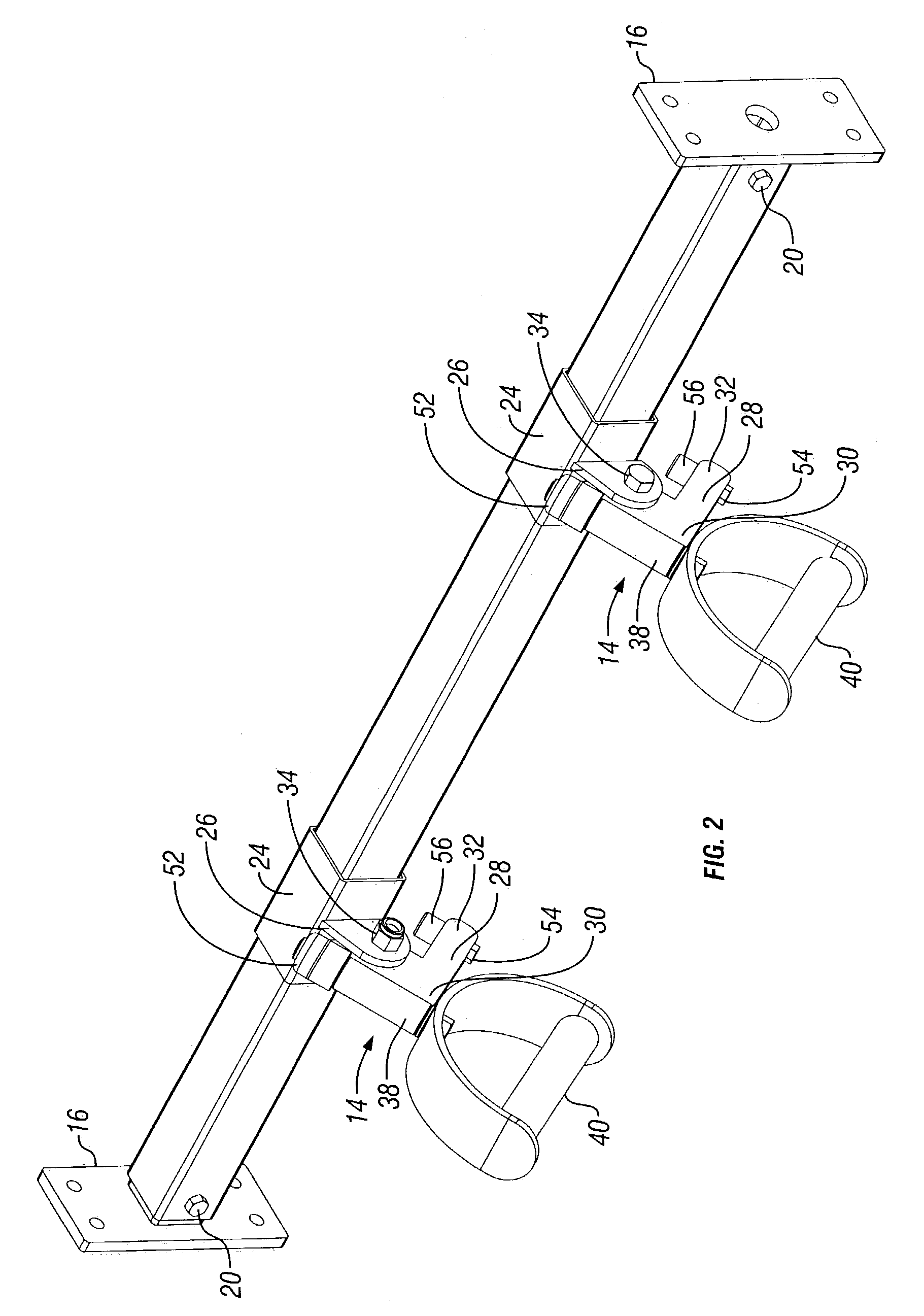
[0018]The improved chin up bar assembly of the present invention is designated in the drawings by the reference numeral 10. The assembly 10 generally includes a cross bar 12 and a pair of handles 14 slidably mounted on the bar 12. Preferably, the cross bar 12 is a square tubular member, as shown in the drawings. However, it is understood that cross bar 12 may be round and / or solid.

[0019]As seen in FIG. 3, a pair of end plates 16 each have a stub shaft 18 which matingly fits into the end of the cross bar 12 and is secured by a bolt 20 and a nut 22. The end plates 16 are adapted to be mounted to uprights (not shown) so as to support the cross bar 12 at a desired height above the ground or floor.

[0020]A pair of collars 24 are slidably mounted on the cross bar 12. Each collar 24 includes a pair of ears 26. Each collar 24 has a hole 27 in the lower surface thereof, as seen in FIG. 4.

[0021]Each handle 14 includes an arm 28 with opposite first and second ends 30, 32. The arm 28 is received...


PUM


Abstract

A chin up bar assembly is provided with a cross bar and a pair of handles slidably mounted on the cross bar. The handles are pivotally mounted for movement between locked and unlocked positions. When a user hangs from the handles, the handles automatically pivot to the locked position to frictionally engage the cross bar and prevent sliding movement of the handles along the cross bar. The handles also can be swiveled during use to exercise different muscles in the user's arms, chest and back.

Description

BACKGROUND OF THE INVENTION[0001]Chin up bars have been known for many years and in general include a cross bar which can be grasped by a user to do chin ups. The user's hands may be spaced at any desired width on the bar to exercise various muscles in the user's arms, back and chest.[0002]More recently, chin up bars have been provided with handles which are slidable along the cross bar so as to adjust the spacing between the user's hands. Such sliding handles include a pin or similar structure received in one of a plurality of holes in the cross bar so as to lock the handles in a selected position. However, such pins are often difficult to actuate or release, and the spacing between the handles is limited to the pre-determined holes in the cross bar.[0003]Therefore, the primary objective of the present invention is the provision of an improved chin up bar assembly.[0004]Another objective of the present invention is the provision of a chin up bar assembly having handles which are sl...

Claims


Application Information

Patent Timeline
IPC IPC(8): A63B21/068A63B1/00
CPCA63B1/00A63B23/12A63B21/1627Y10S482/908A63B2225/09Y10S482/904A63B23/1218A63B23/03533A63B21/4049
Inventor MOBLEY, MITCH T.
Owner CONNER ATHLETIC PRODS
Why Eureka
Try Eureka