Float switch and mounting system assembly

a technology of float switches and mounting systems, which is applied in the direction of liquid/fluent solid measurement, machines/engines, instruments, etc., can solve the problems of float switches that are deficient in many ways, less responsive operation, and risk of overflow or back-up into the system, etc., to achieve cost-effective, widespread distribution and use, and strong construction

Inactive Publication Date: 2006-06-27
RECTORSEAL LLC
View PDF9 Cites 5 Cited by
  • Summary
  • Abstract
  • Description
  • Claims
  • Application Information

AI Technical Summary

Benefits of technology

[0006]The primary object of the present invention is to provide a float switch and mounting system assembly for use with condensate collection pans to shut-off condensate flow when the amount collected exceeds a predetermined depth. It is also an object of the present invention to provide a float switch and mounting system assembly that has cost-effective construction for widespread distribution and use. It is a further object of the present invention to provide a float switch that is sturdy in construction for responsive and reliable operation. A further object of the present invention to provide a float switch and mounting system assembly designed for prompt and cost effective installation. It is also an object of the present invention to provide a float switch and mounting system assembly that is capable of being securely installed and will remain substantially in its original orientation during its entire period of use. Another object of the present invention is to provide a float switch and mounting system assembly with a design that compensates for insubstantial condensate collection pan construction, to prevent the float switch body from leaning in during use. A further object of this invention is to provide a float switch and mounting system assembly that has a means of self-protection against malfunction due to airborne debris, such as the loose insulation fibers typically encountered in attics with some air conditioning applications. In addition, it is a further object of the present invention to provide a float switch and mounting system assembly that is made from corrosion-resistant materials that resist premature deterioration and malfunction.
[0007]As described herein, properly manufactured and used, the present invention would provide a float switch and mounting system assembly that can be used to shut-off the flow of condensate or other fluid when the amount of it collected in a pan or other container associated with the present invention reaches a pre-determined maximum depth. The present invention is typically made from plastic, and thereby impervious to corrosion, which in combination with its sturdy construction avoids premature deterioration. Also, its float switch body is wider than prior art float switches for greater water displacement, and it contains a shroud / housing protects its float switch body from malfunction due to airborne debris, both of which contribute to more responsive and reliable operation than is possible with other prior art float switches capable of fulfilling the same function. In addition, it has three thumbscrews to facilitate and expedite installation, the amount of vertical float switch body displacement is adjustable, its voltage is higher, and its lead wires are longer, all of which make the present invention readily adaptable to a wide variety of applications and changing needs. Further, the thumbscrews provided that prevent the need for drilling holes in a support surface make installation of the present invention efficient and cost-effective, and the design of the present invention provides sturdy and cost-effective construction. In addition, installation of the present invention via its slot, thumbscrews, and crushable friction points provides for secure connection of the present invention to a support surface, even when the support surface is uneven, with the wide and upwardly-extending mounting bracket slot compensating for weak condensate collection pan construction so as to prevent the float switch body from leaning in during use and potentially becoming less responsive. Also, the housing / shroud protects the float switch body against malfunction due to contact with airborne debris, such as but not limited to the loose insulation fibers that are often encountered in attics during air conditioning applications.

Problems solved by technology

When air conditioning condensate and other condensates are collected, there is often a risk of overflow or back-up into the system producing it.
However, currently known float switches are deficient in many ways and thereby subject to malfunction, less responsive operation, more costly installation, and / or unstable installation.
First, the collection pans used for condensate collection do not always have a sturdy construction.
Therefore, when the upstanding pan wall to which a float switch is attached bends as a result of the switch mounting, the float switch tends to lean in over time and when it does it is no longer mounted in a level orientation, making it less responsive.
Further, depending upon the location of the collection pan, a float switch mounted thereto may be at risk for malfunction as a result of airborne debris, such as but not limited to the insulation fibers often encountered in attics where air conditioning system condensing units are located.
Also, prior art liquid-level float switches tend to have float switch bodies that wobble relative to the shaft with which they are associated, a condition that can lead to less responsive operation or malfunction.
Typically, also, the installation of prior art float switches requires the drilling of at least one hole, which increases installation cost.
In addition, some float switches are at risk for premature malfunction as a result of being made from materials that are not completely corrosion-resistant.

Method used


Image

  • Float switch and mounting system assembly
  • Float switch and mounting system assembly
  • Float switch and mounting system assembly

Examples


Embodiment Construction

[0016]While FIGS. 1–7 show the most preferred embodiment of the present invention, it is to be understood that many variations in the present invention are possible and also considered to be a part of the invention disclosed herein, even though such variations are not specifically mentioned or shown. As a result, a reader should determine the scope of the present invention by the appended claims.

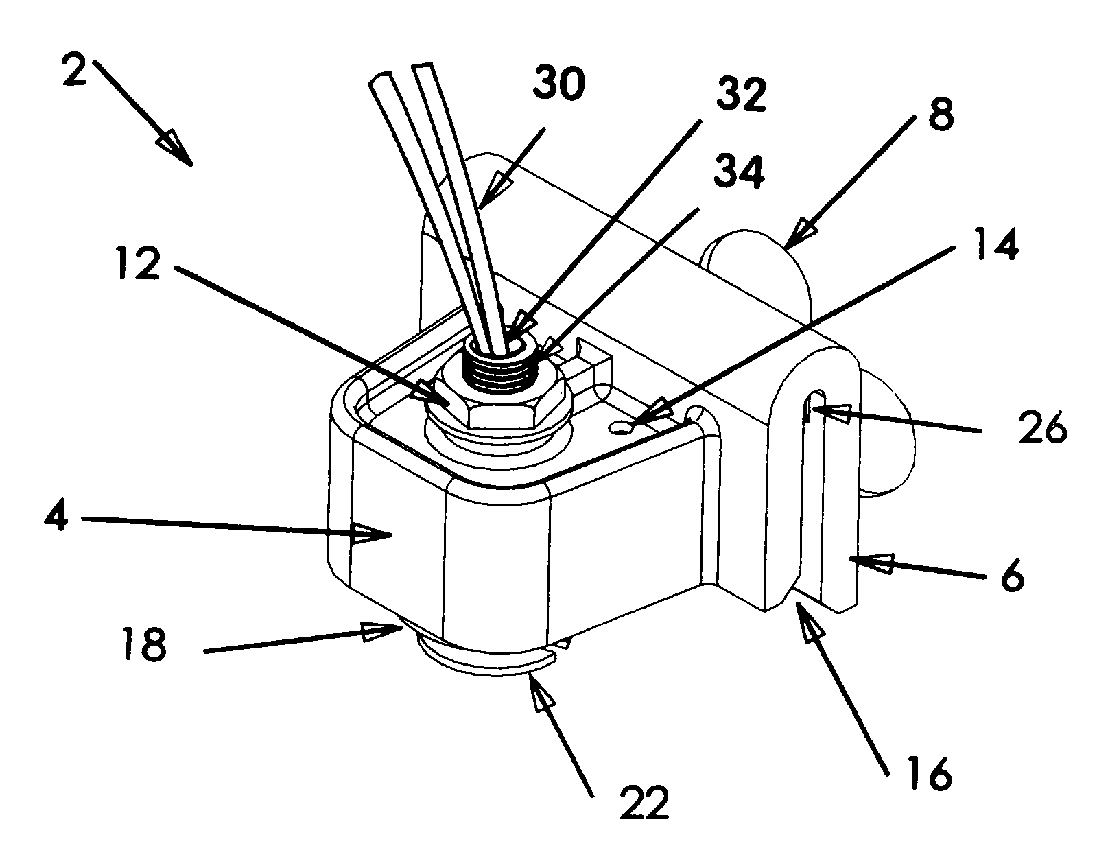
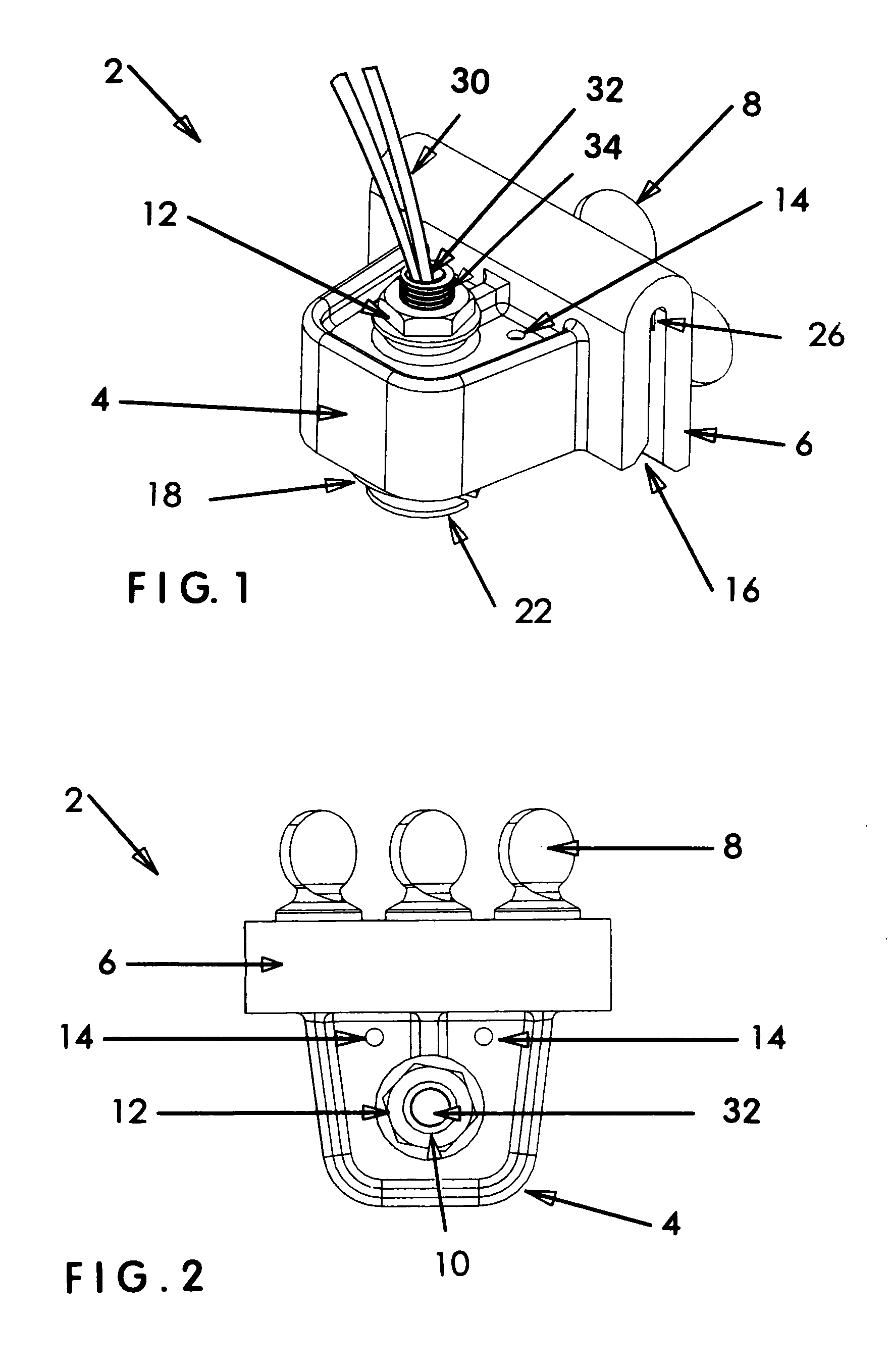
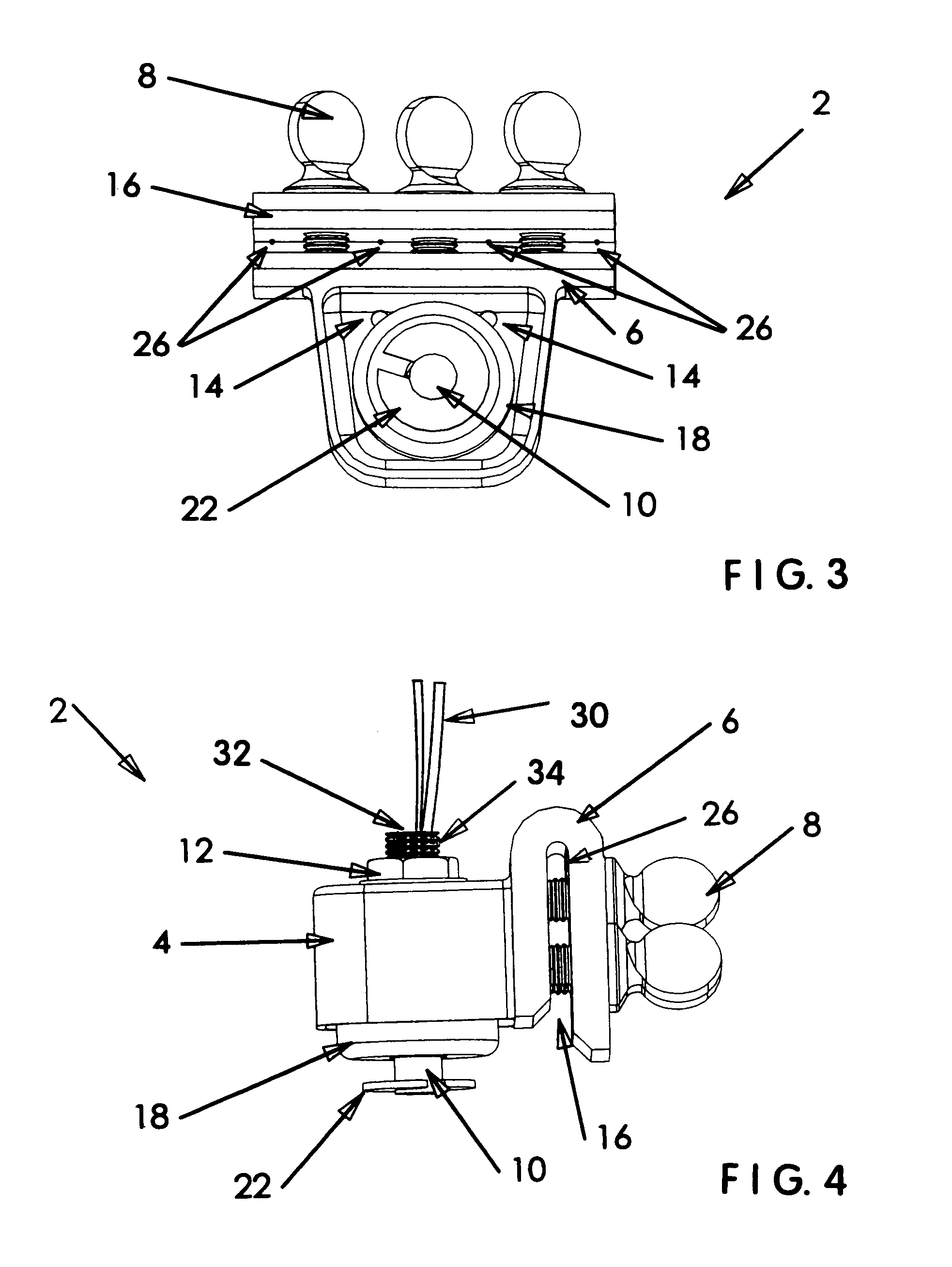
[0017]FIG. 1 shows the most preferred embodiment 2 of the present invention having a protective housing 4 with one visible air vent opening 14 through its top surface, a vertically-oriented shaft 10 with a top opening 32 and a threaded upper end 34 (otherwise hidden in FIG. 1, but visible in FIG. 5) that is secured centrally through the top surface of protective housing 4 by a lock-nut 12, and a U-shaped mounting bracket 6 with an upwardly-extending slot 16 depending from one of the sides of housing 4. FIG. 1 also reveals a float switch body 18 positioned within housing 4 and a disk-shaped s...


PUM


Abstract

A float switch and mounting bracket assembly made from plastic and impervio is to corrosion, with improvements over the prior art including a wide float switch body for enhanced water displacement that results in a more responsive operation, a housing that protects its float switch body from malfunction due to airborne debris, three oversized thumbscrews to facilitate and expedite installation, multiple crushable friction points within the top of the mounting bracket slot that stabilize the orientation of the bracket after installation, and longer lead wires and a higher voltage that allow use of the float switch and mounting bracket assembly in a wide variety of condensate collection and other applications.

Description

CROSS-REFERENCES TO RELATED APPLICATIONS[0001]NoneBACKGROUND OF THE INVENTION[0002]1. Field of the Invention[0003]This invention relates to liquid-level float switches, specifically to a float switch and mounting system assembly of sturdy construction that is primarily contemplated for use in condensate collection applications, but which is also useful in a variety of other applications. The most preferred embodiment of the present invention comprises an adjustable float switch body with the amount of its vertical movement relative to a concentrically positioned shaft being adjustably defined by an upper lock-nut and a disk-shaped bottom stop that are both connected to the shaft, with the float switch body also having a large surface area for enhanced buoyancy and improved responsiveness during operation; a shroud or housing configured and positioned to protect float switch body movement from interference due to airborne debris, with the housing / shroud being closely positioned aroun...

Claims


Application Information

Patent Timeline
Patent Type & Authority Patents(United States)
IPC IPC(8): H01H35/18
CPCH01H35/18
Inventor CANTOLINO, CHRISTOPHER RALPH
Owner RECTORSEAL LLC
Why Eureka
Try Eureka