Float switch and mounting system assembly

Inactive Publication Date: 2006-03-02
CANTOLINO CHRISTOPHER RALPH
View PDF11 Cites 4 Cited by
  • Summary
  • Abstract
  • Description
  • Claims
  • Application Information

AI Technical Summary

Benefits of technology

[0006] The primary object of the present invention is to provide a float switch and mounting system assembly for use with condensate collection pans to shut-off condensate flow when the amount collected exceeds a predetermined depth. It is also an object of the present invention to provide a float switch and mounting system assembly that has cost-effective construction for widespread distribution and use. It is a further object of the present invention to provide a float switch that is sturdy in construction for responsive and reliable operation. A further object of the present invention to provide a float switch and mounting system assembly designed for prompt and cost effective installation. It is also an object of the present invention to provide a float switch and mounting system assembly that is capable of being securely inst

Problems solved by technology

When air conditioning condensate and other condensates are collected, there is often a risk of overflow or back-up into the system producing it.
However, currently known float switches are deficient in many ways and thereby subject to malfunction, less responsive operation, more costly installation, and/or unstable installation.
First, the collection pans used for condensate collection do not always have a sturdy construction.
Therefore, when the upstanding pan wall to which a float switch is attached bends as a result of the switch mounting, the float switch tends to lean in over time and when it does it is no longer mounted in a level orientation, making it less responsive.
Further, depending upon the location of the collection pan,

Method used


Image

  • Float switch and mounting system assembly
  • Float switch and mounting system assembly
  • Float switch and mounting system assembly

Examples


Embodiment Construction

[0017] While FIGS. 1-8 show the most preferred embodiment of the present invention, it is to be understood that many variations in the present invention are possible and also considered to be a part of the invention disclosed herein, even though such variations are not specifically mentioned or shown. As a result, a reader should determine the scope of the present invention by the appended claims.

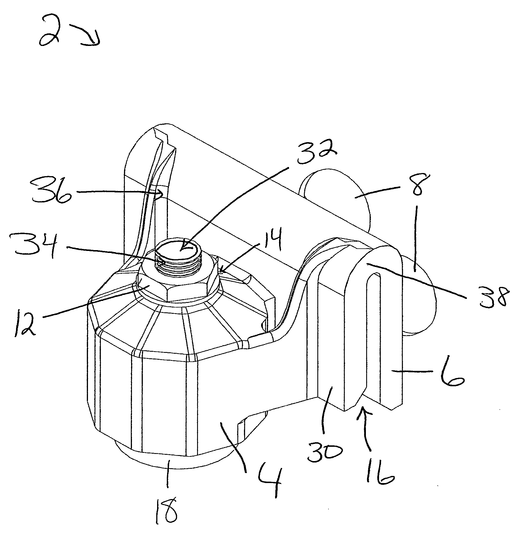
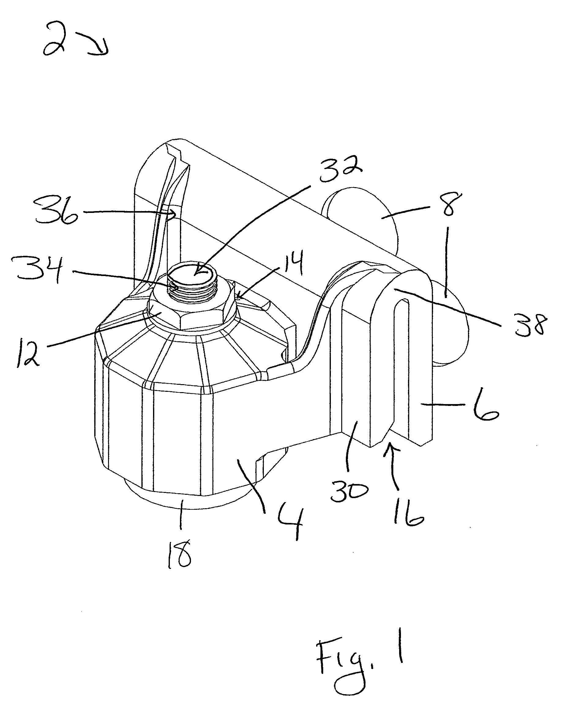
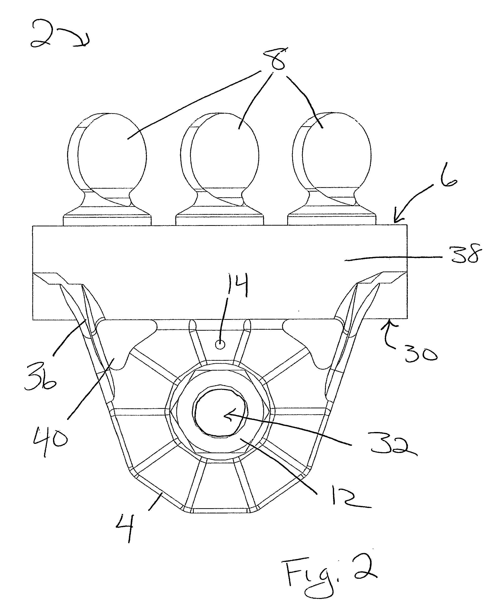
[0018]FIG. 1 shows the most preferred embodiment 2 of the present invention having a protective housing 4 with one air vent opening 14 through its top surface, a vertically-oriented shaft 10 with a top opening 32 and a threaded upper end 34 that is secured centrally through the top surface of protective housing 4 by a lock-nut 12, and a U-shaped mounting bracket having a first arm 30, a web 38, and a second arm 6 with an upwardly-extending slot 16 depending from one of the sides of housing 4. FIG. 1 also reveals a float switch body 18 positioned within housing 4 and a disk-shaped stop 22 b...


PUM


Abstract

A float switch and mounting bracket assembly made from plastic and impervious to corrosion, with improvements over the prior art including a wide float switch body for enhanced water displacement that results in a more responsive operation, a housing that protects its float switch body from malfunction due to airborne debris, three oversized thumbscrews to facilitate and expedite installation, optional crushable friction points within the top of the mounting bracket slot that stabilize the orientation of the bracket after installation, and longer lead wires and a higher voltage that allow use of the present invention assembly in a wide variety of condensate collection and other applications, and also with structural improvements that minimize air hole clogging and provide increased housing strength as well as manufacturing advantages.

Description

CROSS-REFERENCES TO RELATED APPLICATIONS [0001] This application is a continuation-in-part of still pending U.S. Ser. No. 10 / 932,967 filed by the same inventor for substantially the same subject matter on Sep. 2, 2004, with improvements over the invention disclosed in parent application of Ser. No. 10 / 932,967 that include upper surface structural changes that make its air hole is less likely to clog with water / debris, as well as a housing that is structurally stronger to better protect the float and to provide manufacturing advantage.BACKGROUND OF THE INVENTION [0002] 1. Field of the Invention [0003] This invention relates to liquid-level float switches, specifically to a float switch and mounting system assembly of sturdy construction that is primarily contemplated for use in condensate collection applications, but which is also useful in a variety of other applications. The most preferred embodiment of the present invention comprises an adjustable float switch body with the amount...

Claims


Application Information

Patent Timeline
IPC IPC(8): H01H35/18
CPCH01H35/18
Inventor CANTOLINO, CHRISTOPHER RALPH
Owner CANTOLINO CHRISTOPHER RALPH
Why Eureka
Try Eureka