Plastic pan float switch and mounting system assembly

a float switch and mounting system technology, applied in liquid/fluent solid measurement, instruments, machines/engines, etc., can solve the problems of float switch deficiency in many ways, less responsive operation, and risk of overflow or back-up into the system, and achieve cost-effective, widespread distribution and use, and sturdy construction

Inactive Publication Date: 2006-01-31
RECTORSEAL LLC
View PDF10 Cites 8 Cited by
  • Summary
  • Abstract
  • Description
  • Claims
  • Application Information

AI Technical Summary

Benefits of technology

[0006]The primary object of the present invention is to provide a float switch and mounting system assembly for use with plastic condensate collection pans to shut-off condensate flow when the amount collected exceeds a predetermined depth. It is also an object of the present invention to provide a float switch and mounting system assembly that has cost-effective construction for widespread distribution and use. It is a further object of the present invention to provide a float switch that is sturdy in construction for responsive and reliable operation. A further object of the present invention to provide a float switch and mounting system assembly designed for prompt and cost effective installation. It is also an object of the present invention to provide a float switch and mounting system assembly that is adjustable and capable of being securely installed and thereafter remain substantially in its original orientation during its entire period of use. Another object of the present invention is to provide a float switch and mounting system assembly with a design that compensates for insubstantial condensate collection pan construction, to prevent the float switch body from leaning in during use. A further object of this invention is to provide a float switch and mounting system assembly that has a means of self-protection against malfunction due to airborne debris, such as the loose insulation fibers typically encountered in attics with some air conditioning applications. In addition, it is a further object of the present invention to provide a float switch and mounting system assembly that is made from corrosion-resistant materials that resist premature deterioration and malfunction.

Problems solved by technology

When air conditioning condensate and other condensates are collected, there is often a risk of overflow or back-up into the system producing it.
However, currently known float switches are deficient in many ways and thereby subject to malfunction, less responsive operation, more costly installation, and / or unstable installation.
First, the collection pans used for condensate collection do not always have a sturdy construction.
Therefore, when the upstanding pan wall to which a float switch is attached bends as a result of the switch mounting, the float switch tends to lean in over time and when it does it is no longer mounted in a level orientation, making it less responsive.
Also, the plastic pans used can have varying upper edge configurations and a mounting bracket that securely attaches a switch / housing to one pan so as to achieve proper float switch function, may not be able to securely attach the float switch to a pan with a different upper edge thickness or configuration.
Further, depending upon the location of the collection pan, a float switch mounted thereto may be at risk for malfunction as a result of airborne debris, such as but not limited to the insulation fibers often encountered in attics where air conditioning system condensing units are located.
Also, prior art liquid-level float switches tend to have float switch bodies that wobble relative to the shaft with which they are associated, a condition that can lead to less responsive operation or malfunction.
Typically, also, the installation of prior art float switches requires the drilling of at least one hole through the support surface or pan, which increases installation cost.
In addition, some float switches are at risk for premature malfunction as a result of being made from materials that are not completely corrosion-resistant.

Method used


Image

  • Plastic pan float switch and mounting system assembly
  • Plastic pan float switch and mounting system assembly
  • Plastic pan float switch and mounting system assembly

Examples


Embodiment Construction

[0029]While FIGS. 1–20 show the most preferred embodiment of the present invention, it is to be understood that many variations in the present invention are possible and also considered to be a part of the invention disclosed herein, even though such variations are not specifically mentioned or shown. As a result, a reader should determine the scope of the present invention by the appended claims.

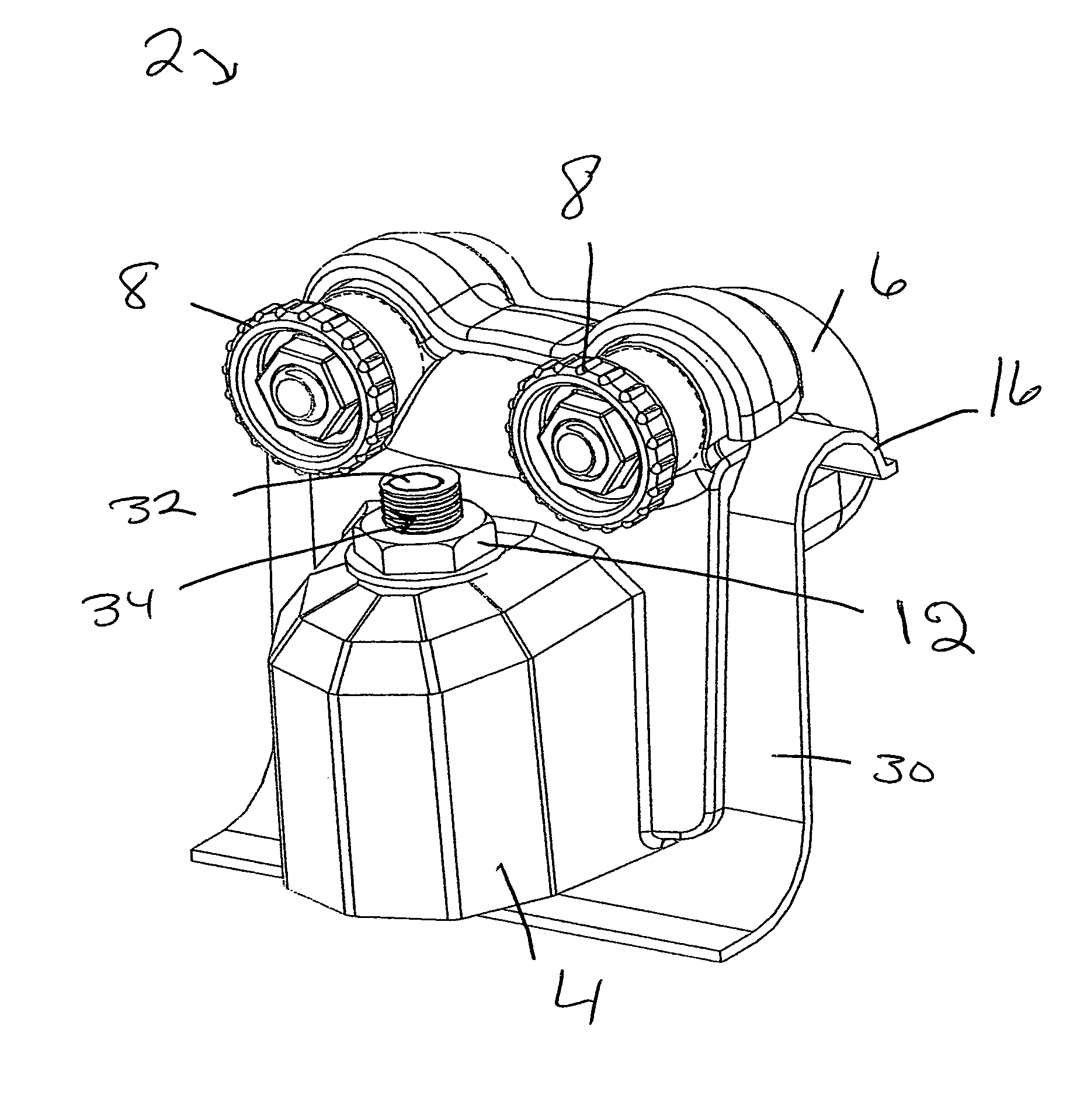
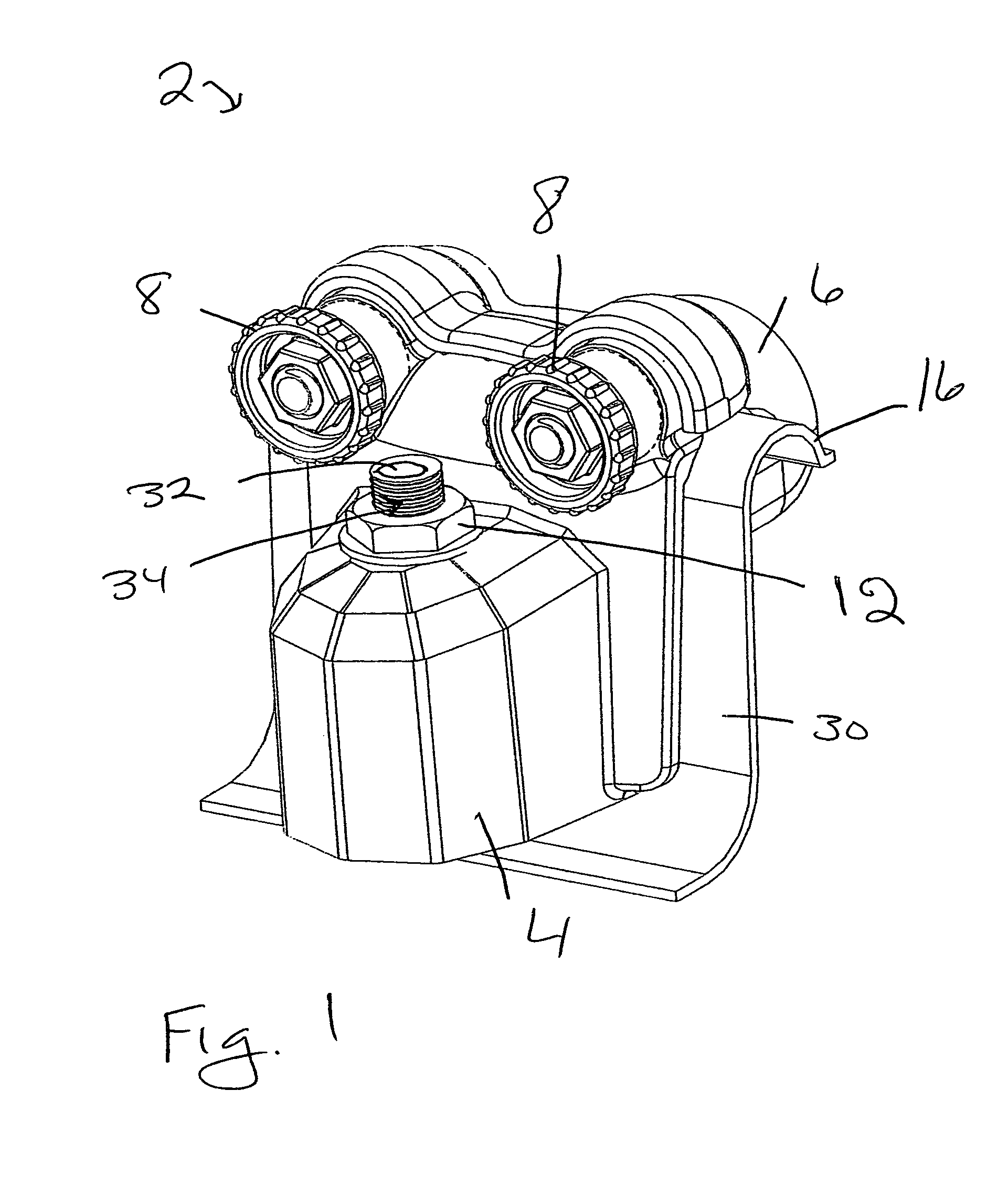
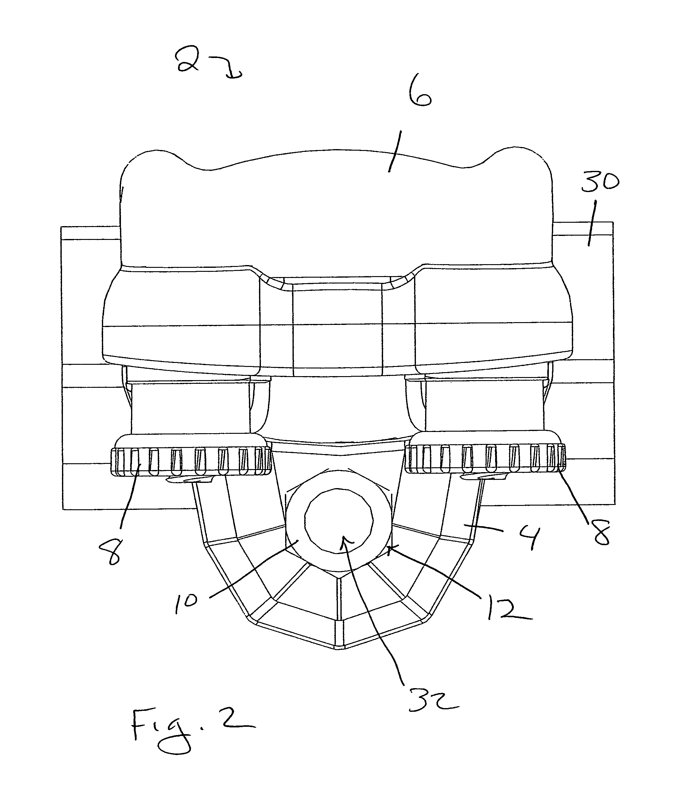
[0030]FIG. 1 shows the most preferred embodiment 2 of the present invention having a protective housing 4, a vertically-oriented shaft (identified in FIG. 9 by the number 10) that is secured centrally through the top surface of protective housing 4 by a lock-nut 12 and with shaft 10 having a top opening 32 and a threaded upper end 34. FIG. 1 also shows a clamping member 6 attached to housing 4 via two nuts 8. Although the two nut 8 configuration is preferred, housing 4 and clamping member 6 could be configured for connection with more or less than the two nuts 8 shown in FIG. 1. FIG. 1 furt...


PUM


Abstract

A float switch, housing, and clamping member assembly that is made from plastic and impervious to corrosion, with improvements over the prior art including a wide float switch body for enhanced water displacement that results in a more responsive operation, a housing configured to protect its float switch body from malfunction due to airborne debris, a clamping member configured to create a J-shaped slot between it and the housing when they are connected together over the upper edge of a support surface, such as a plastic condensate collection pan with a flange. Oversized thumbscrews facilitate and expedite installation. Strength-enhancing ribs are associated with the housing and clamping member. Connection between the housing and clamping member can also include a ratcheting configuration.

Description

CROSS-REFERENCES TO RELATED APPLICATIONS[0001]This application is a continuation-in-part of still pending U.S. Ser. No. 10 / 932,967 filed by the same inventor for substantially the same subject matter on Sep. 2, 2004, with improvements over the invention disclosed in parent application Ser. No. 10 / 932,967 that primarily include a two-part housing / clamp structure that creates a J-shaped slot which is able to accommodate a variety of plastic condensate collection pans having different upper edge configurations, that optionally can includes a ratcheting arrangement between the clamping member and the housing to better secure the upper edge of a plastic condensate collection pan within the J-shaped slot, that has ribs which add strength to the housing and clamping member, and that has a rearward location in the housing for its air vent holes which make them less likely to become clogged with water, algae, and / or debris.BACKGROUND OF THE INVENTION[0002]1. Field of the Invention[0003]This ...

Claims


Application Information

Patent Timeline
Patent Type & Authority Patents(United States)
IPC IPC(8): H01H35/18
CPCH01H35/18
Inventor CANTOLINO, CHRISTOPHER RALPH
Owner RECTORSEAL LLC
Why Eureka
Try Eureka