Doppler complex FFT police radar with direction sensing capability
Inactive Publication Date: 2006-06-27
APPLIED CONCEPTS
View PDF37 Cites 18 Cited by
- Summary
- Abstract
- Description
- Claims
- Application Information
AI Technical Summary
Benefits of technology
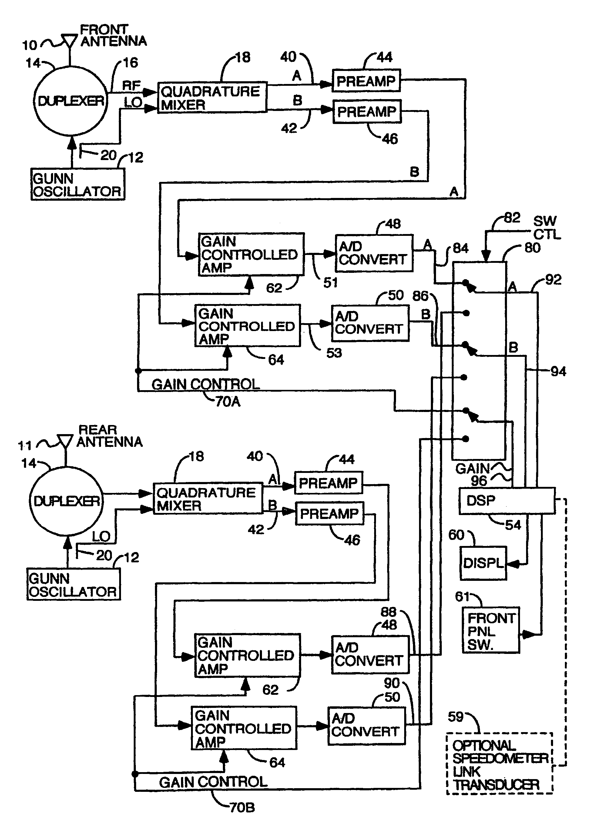
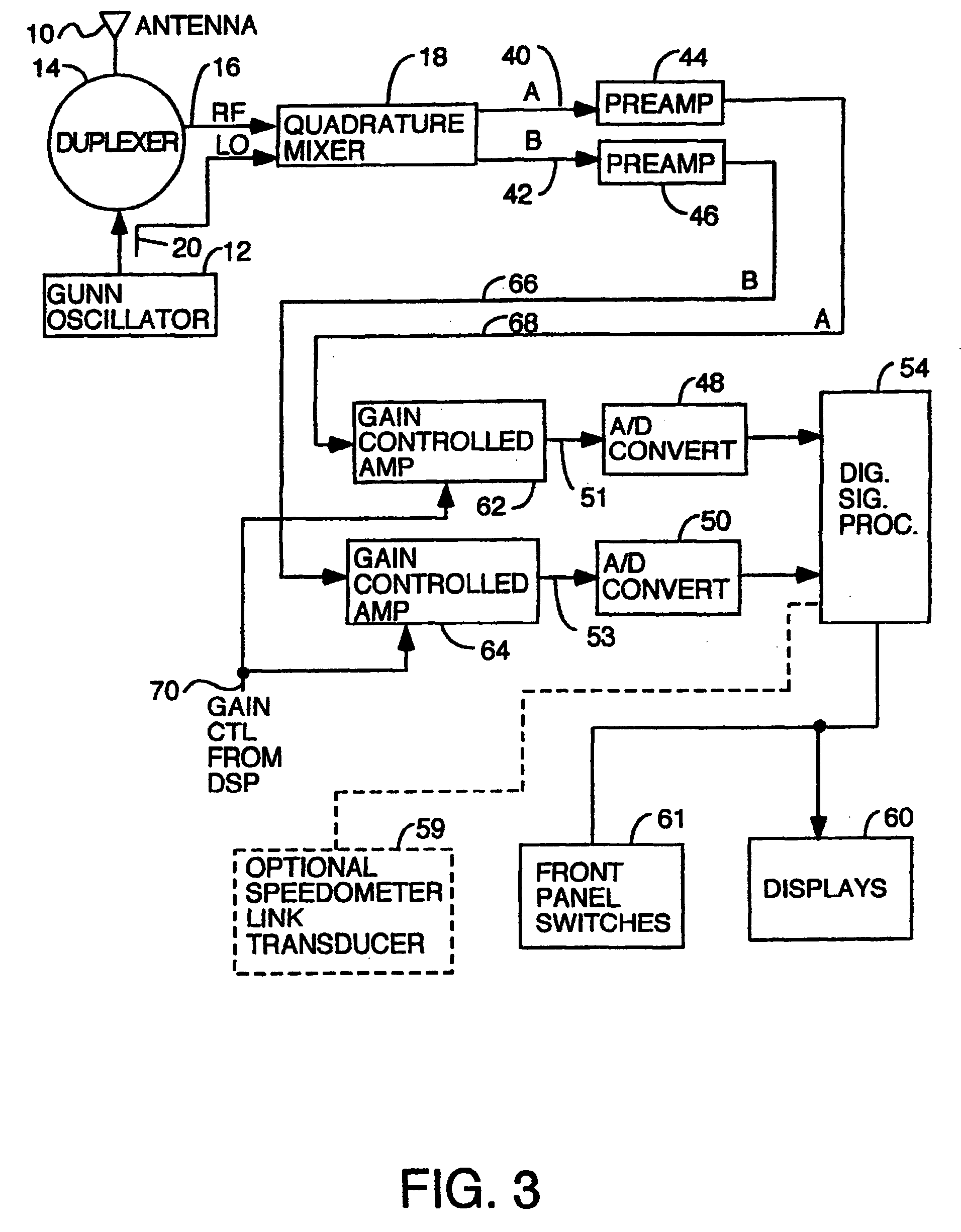
[0028]A further degree of refinement in the fastest target screening process is provided by using the controlled gain amplifiers to amplify the doppler signals before they are digitized. By knowing the gain that was in effect as each batch of samples were gathered, it is possible to calculate the true power of any signal in the spectrum from its apparent or relative power and the gain that was in effect when the samples were collected. This allows fastest target candidates to be not rejected even if they are at a frequency that is a double or triple of the patrol speed or a strong signal if the patrol speed or strong s
Problems solved by technology
It is possible that the direction sensing circuitry will tell the PLL circuitry the directio
Method used
View moreImage
Smart ImageViewing Examples

Examples
 PUM
 Abstract
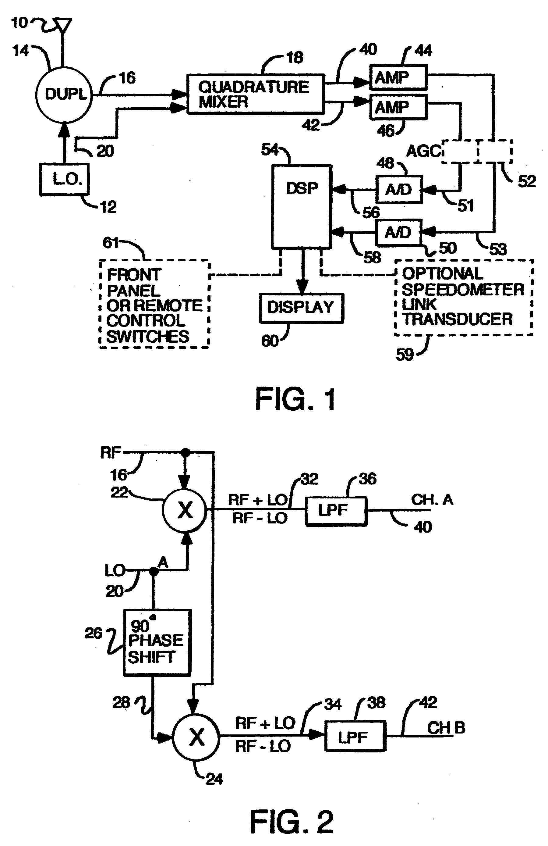
A series of police Doppler single mode radars and a multimode police Doppler radar, all with direction sensing capability are disclosed. A quadrature front end which mixes received RF with a local oscillator to generate two channels of Doppler signals, one channel being shifted by an integer multiple of 90 degrees in phase relative to the other by shifting either the RF or the local oscillator signal being fed to one mixer but not the other. The two Doppler signals are digitized and the samples are processed by a digital signal processor programmed to find one or more selected target speeds. Single modes disclosed are: stationary strongest target; stationary, fastest target; stationary, strongest and fastest targets; moving, strongest, opposite lane; moving, strongest, same lane; moving, fastest, opposite lane; moving, fastest and strongest, opposite lane; moving, fastest, same lane; moving fastest and strongest, same lane.
Description
[0001]This application is a continuation of application Ser. No. 10 / 005,553 filed Nov. 7, 2001, now U.S. Pat. No. 6,646,591; which is a continuation of application Ser. No. 09 / 690,179 filed Oct. 16, 2000, abandoned; which is a continuation of application Ser. No. 09 / 120,542 filed Jul. 21, 1998, now U.S. Pat. No. 6,198,427.TECHNICAL FIELD OF THE INVENTION[0002]The invention is useful in the field of traffic surveillance radars.BACKGROUND OF THE INVENTION[0003]In certain multitarget situations when traffic is being observed by a police Doppler radar in the same lane as the patrol car and in the opposite lane, it is useful to be able to limit the targets whose speeds are displayed to targets only in the same lane or only in the opposite lane. The same is true for stationary operation at the roadside. Further, it is useful to be able to use the radar to search for only the strongest target or both the strongest target and the fastest target or only the fastest target.[0004]Police Dopple...
Claims
Login to View More Application Information
Patent Timeline
 IPC IPC(8): G01S13/58G01S13/00G01S7/04G01S7/288
CPCG01S7/04G01S13/589G01S2007/2883G01S7/2883
Inventor AKER, JOHN L.GAMMENTHALER, ROBERT S.
Owner APPLIED CONCEPTS
Features
- R&D
- Intellectual Property
- Life Sciences
- Materials
- Tech Scout
- Unparalleled Data Quality
- Higher Quality Content
- 60% Fewer Hallucinations
Learn More Browse by: Latest US Patents, China's latest patents, Technical Efficacy Thesaurus, Application Domain, Technology Topic, Popular Technical Reports.
© 2025 PatSnap. All rights reserved.Legal|Privacy policy|Modern Slavery Act Transparency Statement|Sitemap|About US| Contact US: help@patsnap.com