Method and apparatus for a reflective spatial light modulator with a flexible pedestal

a technology of spatial light modulator and flexible pedestal, applied in the field of manufacturing objects, can solve the problems of complex mechanical structure reliability and lifetime concerns, difficult manufacturing of torsion spring designs, and inconvenient use, and achieves simple structure, high device yield per wafer, and convenient use.

Active Publication Date: 2006-06-27
MIRADIA INC
View PDF64 Cites 57 Cited by
  • Summary
  • Abstract
  • Description
  • Claims
  • Application Information

AI Technical Summary

Benefits of technology

[0008]Many benefits are achieved by way of the present invention over conventional techniques. For example, the present technique provides an easy to use process that relies upon conventional technology. In some embodiments, the method provides higher device yields in dies per wafer. Additionally, the method provides a process that is compatible with conventional process technology without substantial modifications to conventional equipment and processes. Preferably, the invention provides a simple structure with fewer process steps, higher yields, reliability, and other desirable features in certain embodiments. Depending upon the embodiment, one or more of these benefits may be achieved. These and other benefits will be described in more throughout the present specification and more particularly below.

Problems solved by technology

Unfortunately, these techniques also have limitations.
For example, some torsion spring designs are difficult to manufacture owing to their complex structural features.
Moreover, complex mechanical structures may have reliability and lifetime concerns.

Method used


Image

  • Method and apparatus for a reflective spatial light modulator with a flexible pedestal
  • Method and apparatus for a reflective spatial light modulator with a flexible pedestal
  • Method and apparatus for a reflective spatial light modulator with a flexible pedestal

Examples


Embodiment Construction

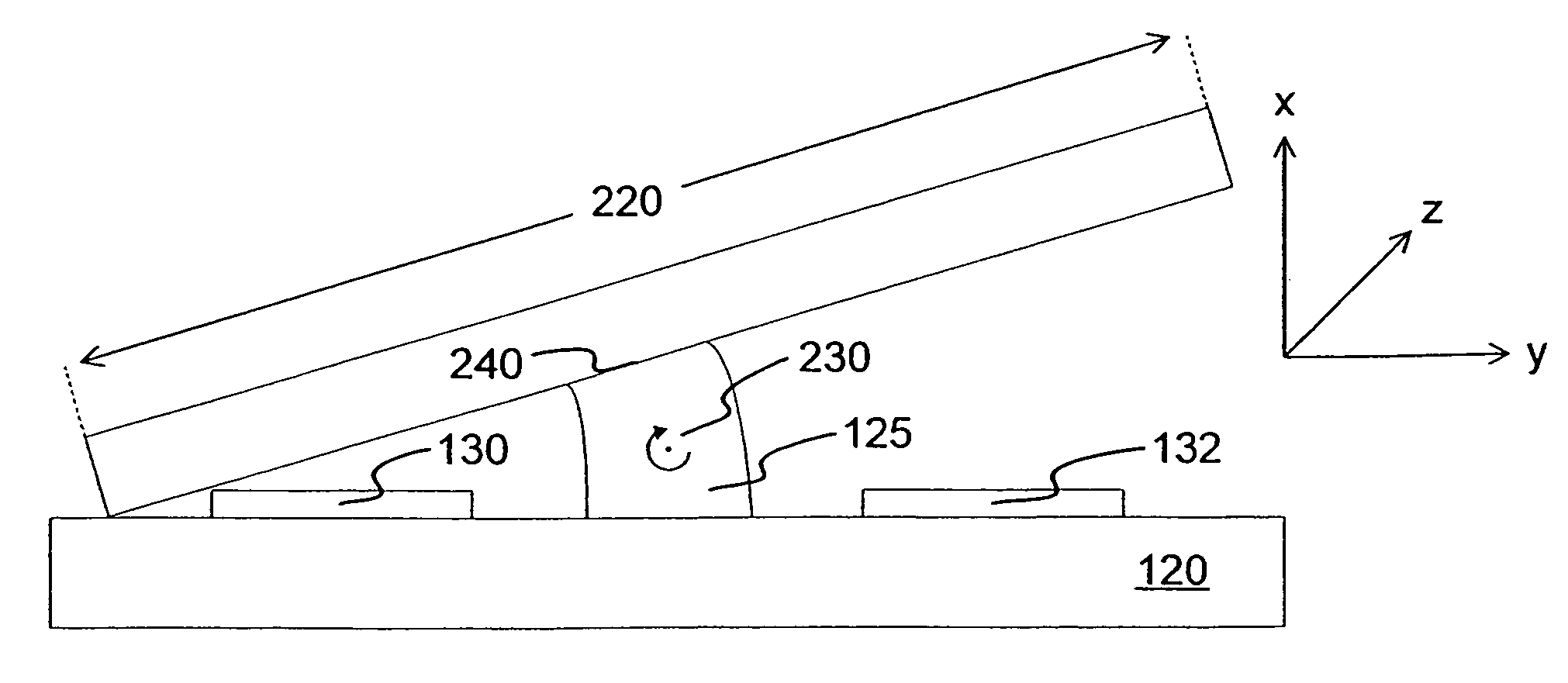
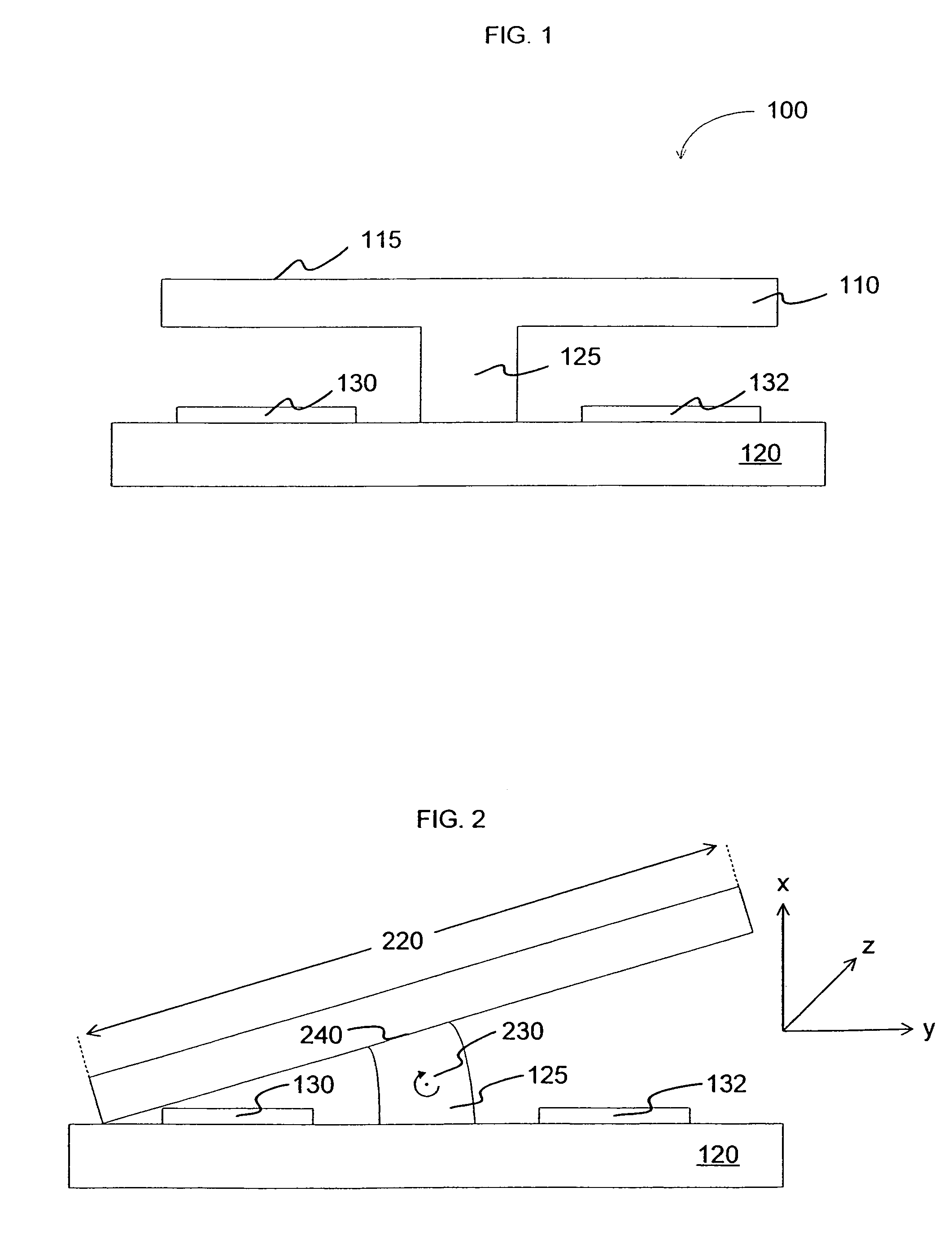
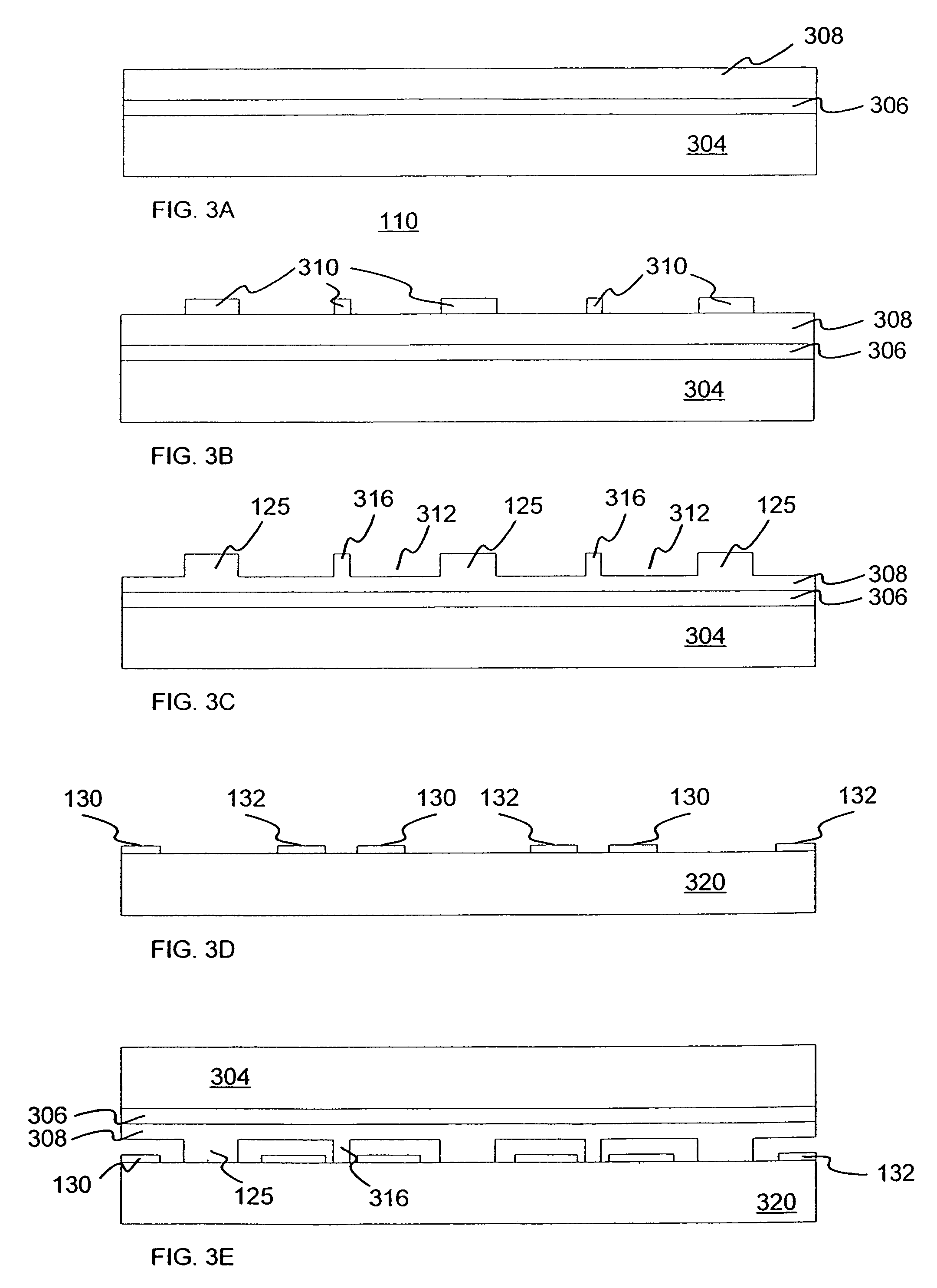
[0017]FIG. 1 is a simplified schematic side view of a micro-electromechanical system with a flexible pedestal according to an embodiment of the present invention. A first surface 120 is provided with at least one electrically activated electrode 130 coupled to the first surface. The first surface can be made of any suitable material. The suitable material generally has mechanical stability and an ability to be processed using semiconductor processing techniques. As merely an example, the material can be a semiconductor. Preferably, the first surface is made from a single crystal silicon wafer, processed according to semiconductor processing techniques. In one embodiment, the first surface includes a plurality of control electronics and other integrated circuits formed using semiconductor processing techniques. Other materials may also be used in alternative embodiments according to the present invention.

[0018]Electrically activated electrodes 130 and 132 are coupled to the first sur...


PUM


Abstract

An electro-mechanical system comprising a substrate including a surface region and a flexible member coupled at a first end to the surface region. The system further comprises a base region within a first portion of the flexible member and a tip region within a second portion of the flexible member. The system also comprises a reflective member coupled to the flexible member, including a reflective surface and a backside region, the backside region being coupled to the second end of the flexible member, the reflective surface being substantially parallel to the surface region while the reflective member is in a first state and being substantially non-parallel to the surface region while the reflective member is in a second state, whereupon the flexible member moves from a first position characterized by the first state to a second position characterized by the second state.

Description

BACKGROUND OF THE INVENTION[0001]This present invention relates generally to manufacturing objects. More particularly, the invention provides a method and apparatus for fabricating and operating electro-mechanical systems. Merely by way of example, the invention has been applied to a high fill factor micro-electro-mechanical mirror array with a hidden, flexible support pedestal. The method and apparatus can be applied to other electro-mechanical technology as well, including actuators and sensors.[0002]Micro-electromechanical systems (MEMS) are used in a number of application areas. For example, MEMS have been used in micro-mirror arrays, sensors, and actuators. In some of these applications, a suspended member is supported by a flexible hinge attached to a stationary portion of the mirco-mirror array. Flexibly attached to the hinge, the suspended member is attracted to an electrode upon application of an electrical force and restored to an original position by a restoring force. In...

Claims


Application Information

Patent Timeline
Patent Type & Authority Patents(United States)
IPC IPC(8): G02B26/00
CPCG02B26/0841
Inventor YANG, XIAO
Owner MIRADIA INC
Why Eureka
Try Eureka