Cable network redundancy architecture

a network redundancy and cable technology, applied in the field of digital cable network technology, can solve the problems of extremely undesirable type of disruption or delay in service, difficult task of providing reliable high-quality voice/video communication over such networks, etc., and achieve the effect of transparent cable modems

Inactive Publication Date: 2006-06-27
CISCO TECH INC
View PDF28 Cites 52 Cited by
  • Summary
  • Abstract
  • Description
  • Claims
  • Application Information

AI Technical Summary

Benefits of technology

[0010]The present invention meets these needs by providing a CMTS redundancy technique with associated methods and apparatus. Redundancy requires at least two CMTS interfaces (e.g., line cards) on one or more CMTS chassis at the head end of a cable network. One of the CMTS interfaces (“CMTS” hereinafter) serves as a backup or “protecting” CMTS. When another CMTS (a “working” CMTS) becomes unavailable to service its group of cable modems, the protecting CMTS takes over service to those cable modems. The switchover takes place transparently (or nearly transparently) to the cable modems. Preferably, the protecting CMTS provides service on the same downstream channel as used by the working CMTS. Preferably, the cable modems need not modify any settings pursuant to their cable modem communication protocol (e.g., DOCSIS ranging). This transparency to the cable modems is realized by keeping the working and protecting CMTSs in synchronization regarding service parameters for the cable modems. In other words, the protecting CMTS maintains a list of current parameters for allowing service to the cable modems.

Problems solved by technology

For networks that use a shared access medium to communicate between subscribers and the service provider (e.g., cable networks, wireless networks, etc.), providing reliable high-quality voice / video communication over such networks is not an easy task.
In addition, because cable modems were not used, the head end of pre-HFC cable systems did not contain a CMTS.
Therefore, a failure of the one of the CMTS will result in a service disruption or service outage of the cable modems relying upon the failed element.
If a CMTS fails, for example, it may have to be repaired or replaced before service can resume.
From the perspective of the service provider and the end user, any type of disruption or delay in service is extremely undesirable.
This problem becomes particularly acute as broadband access technologies, including cable, move toward digital telephony (e.g., Voice over IP or “VoIP”).

Method used


Image

  • Cable network redundancy architecture
  • Cable network redundancy architecture
  • Cable network redundancy architecture

Examples


Embodiment Construction
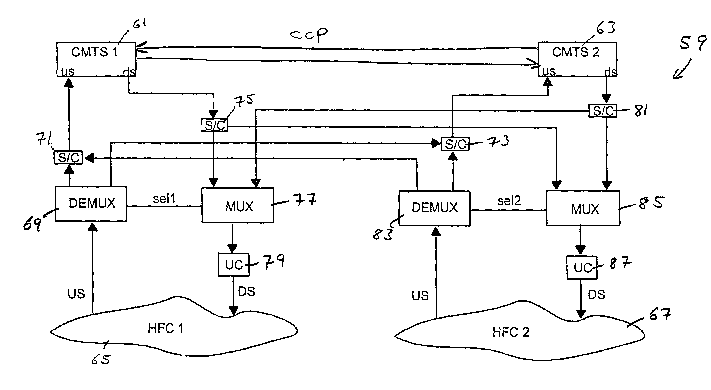
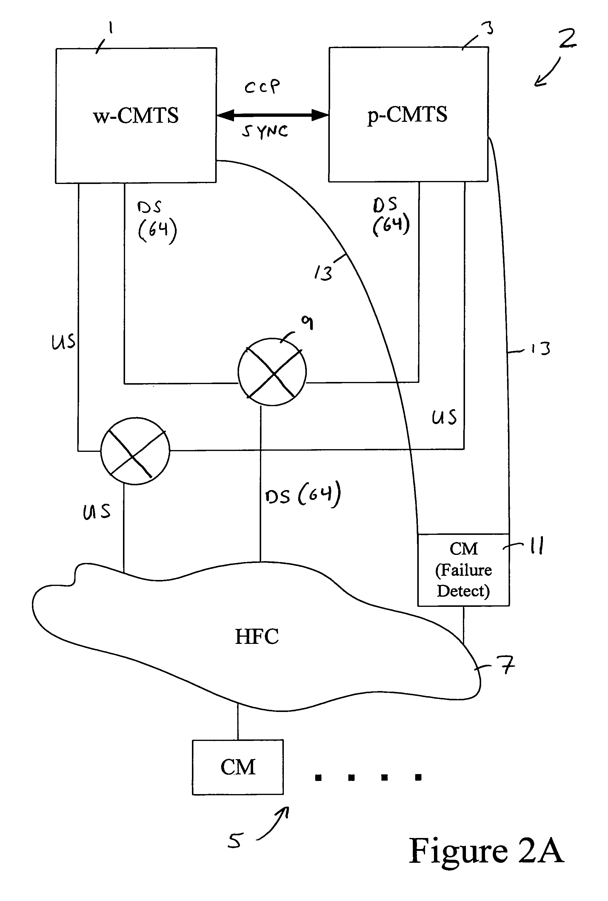
[0027]I. Overview

[0028]The present invention may be implemented in many ways. Generally, the invention employs two or more CMTSs or CMTS interfaces: one active CMTS which services a group of cable modems and one standby CMTS which is ready to take over service to those cable modems should the active CMTS become unavailable for any reason.

[0029]While the following description regularly refers to “CMTSs,” the network entities participating in this invention are not limited to CMTSs per se. One or both of the active and standby “CMTSs” could actually be a separate CMTS interface or line card. Possibly both the active and standby CMTSs are interfaces provided in the same CMTS chassis.

[0030]The terms “working CMTS” and “protecting CMTS” specify fixed types of CMTS. The working and protection statuses of the CMTSs never change, regardless of whether those CMTSs are actively servicing cable modems. The term “active CMTS” and “standby CMTS” refer to the dynamic states of CMTSs. An active CM...


PUM


Abstract

A CMTS redundancy technique requires at least two CMTS interfaces (e.g., line cards) on one or more CMTS chassis at the head end of a cable network. One of the CMTSs serves as a backup or “protecting” CMTS. When another CMTS (a “working” CMTS) becomes unavailable to service its group of cable modems, the protecting CMTS takes over service to those cable modems. The SWITCHOVER takes place transparently (or nearly transparently) to the cable modems. The protecting CMTS provides service on the same downstream channel as used by the working CMTS. The cable modems need not modify any settings pursuant to their cable modem communication protocol (e.g., DOCSIS ranging). This transparency to the cable modems is realized by keeping the working and protecting CMTSs in synchronization regarding service parameters for the cable modems. In other words, the protecting CMTS maintains a list of current parameters for allowing service to the cable modems.

Description

[0001]This invention is related to the following U.S. Patent Applications: U.S. patent application Ser. No. 09 / 484,189, filed on the same day as this patent application, naming Daruwalla, Forster, Roeck, Woundy, and Thomas as inventors, and titled “ROUTING PROTOCOL BASED REDUNDANCY DESIGN FOR SHARED-ACCESS NETWORKS”; and U.S. patent application Ser. No. 09 / 484,611, filed on the same day as this patent application, naming Daruwalla, Forster, Roeck, Chapman, Zang, and Lu as inventors, and titled “METHOD FOR A CABLE MODEM TO RAPIDLY SWITCH TO A BACKUP CMTS”. These applications are incorporated herein by reference in their entireties and for all purposes.BACKGROUND OF THE INVENTION[0002]This invention relates to digital cable network technology. More specifically, it relates to methods and apparatus that provide redundancy for critical headend components of digital cable networks.[0003]Broadband access technologies such as cable, fiber optic, and wireless have made rapid progress in rec...

Claims


Application Information

Patent Timeline
Patent Type & Authority Patents(United States)
IPC IPC(8): H04B1/38
CPCG06F11/2005H04N21/64738H04N7/173H04L29/12009H04L61/00
Inventor ZANG, JOANNA QUNDARUWALLA, FEISALFORSTER, JAMES R.ROECK, GUENTER E.O'DONNELL, JOSEPHCHEN, JOHNMILLET, MARK
Owner CISCO TECH INC
Why Eureka
Try Eureka