

Method and apparatus for coupling structures to roofing
a technology of coupling structure and roof, applied in the field of coupling structure to roof, can solve the problems of roof leakage, snow guard torn from the roof, and the trailing edge of the snow guard to lift from the roo
- Summary
- Abstract
- Description
- Claims
- Application Information
AI Technical Summary
Problems solved by technology
Method used
Image

Examples
first embodiment
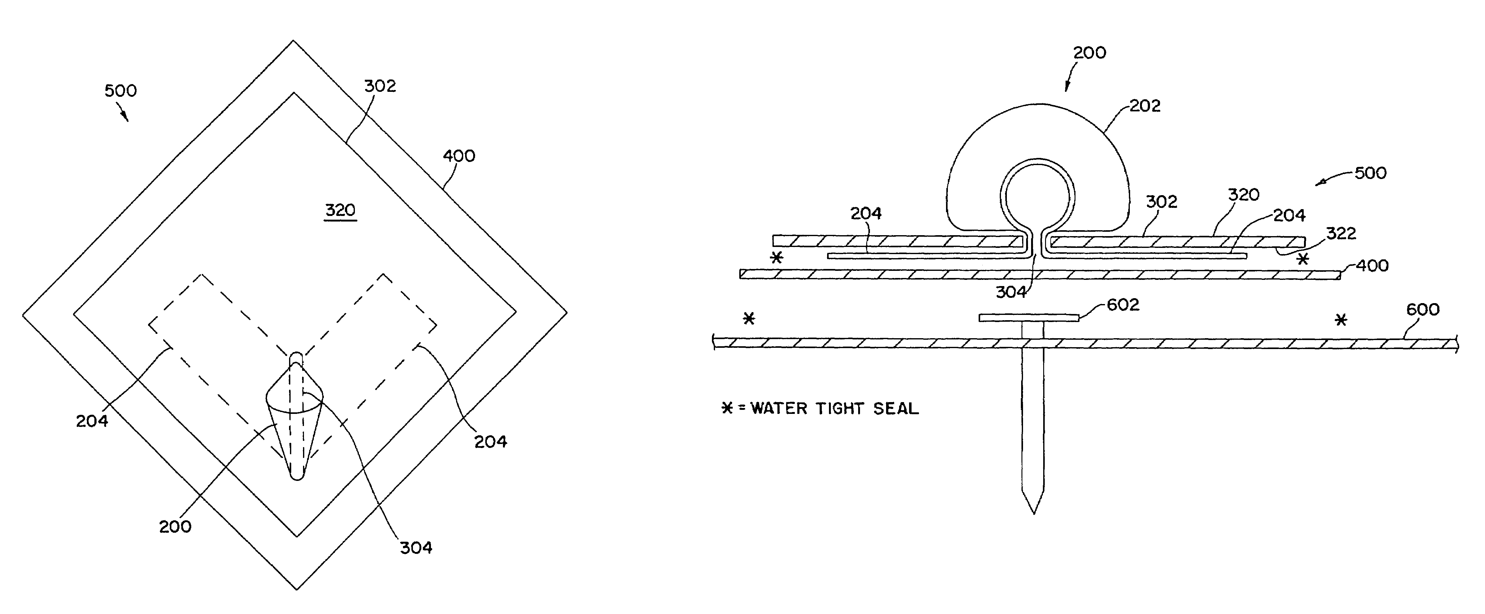
[0034]FIG. 5A is an exploded profile view of a first embodiment snow guard assembly 500 being bonded to a roof membrane 600. The pocket 202 is disposed adjacent a first surface 320 of the first membrane 302 and the tabs 204 are disposed adjacent the second surface 322 of the first membrane 302. An installer may drive a mechanical fastener 602, preferably a roofing screw and plate, through the roof sheathing 600 and into the roof decking 112A, 112B, and 112C in the desired location. The installer may then bond the second membrane 400 to the roof sheathing 600 along the perimeter of the second membrane 400, preferably within 0.5″ to 1″ of the perimeter. The installer may use hot air welding or a butylene pressure sensitive tape, or the like, to form a watertight seal. The mechanical fastener 602 may provide a local attachment point for the roof sheathing 600 to the roof decking 112A, 112B, and 112C.
second embodiment
[0035]FIG. 5B is an exploded profile view of a second embodiment snow guard assembly 500′ being bonded to a roof membrane 600. The snow guard assembly 500′ may include a membrane 302 having an opening 304 extending from a first surface 320 of the first membrane 302 to a second surface 322 of the first membrane 302, and a snow guard 200 having a pocket 202 coupled to at least one tab 204. The pocket 202 is disposed adjacent the first surface 320 of the membrane 302 and the tab 204 is disposed adjacent the second surface 322 of the membrane 302. In this embodiment, the snow guard assembly 500′ may be bonded directly to the roof membrane 600 without the need of a second, intermediate membrane.
[0036]FIG. 6 is a top view of a roof 700 illustrating an installation of the snow guard assembly 500. As shown in FIG. 6, the snow guard assemblies 500 may be secured in a predetermined and structured pattern. As an example, the assemblies 500 may be spaced on a square grid separated by a height H...
third embodiment
[0038]In accordance with the invention, a snow guard assembly may have a snow guard 200 formed from a polymeric material and may be bonded to the first membrane 302 using ultrasonic welding.
[0039]In the unfortunate event that an excessive snowfall tears a snow guard 200 from the snow guard assembly 500, an installer may simply place a larger snow guard assembly over the prior snow guard assembly and bonded it to the roof membrane.
[0040]FIG. 7A is a perspective view of a cable holder 700 that maybe coupled to roofing via use of the present method and apparatus, as described below. In accordance with a first exemplary embodiment of the cable holder 700, the cable holder 700 may be made of metallic or polymeric material. In addition, the cable holder 700 may be made of identical cable holder halves 704A and 704B that cooperate to hold a cable 702, typically a braided copper cable, a spaced distance above a membrane roof 600 (See FIG. 9). The cable holder halves 704A and 704B may have a...
PUM
| Property | Measurement | Unit |
|---|---|---|
| Time | aaaaa | aaaaa |
| Angle | aaaaa | aaaaa |
| Angle | aaaaa | aaaaa |
Abstract
Description
Claims
Application Information