Workpiece beveling machine

a workpiece and beveling technology, applied in the field of beveling machines, can solve the problems of uneven straightness, thickness and width of the floor strip, and insufficient prior practice,

Active Publication Date: 2006-07-04
HASKO
View PDF20 Cites 22 Cited by
  • Summary
  • Abstract
  • Description
  • Claims
  • Application Information

AI Technical Summary

Problems solved by technology

Such flooring strips are not always of uniform straightness, thickness, and width, and when the individual strips are formed into a finished floor, there can be raised edges which can catch the heel of a person walking on the surface.
However, this prior practice is not entirely satisfactory since the non-uniformity of the flooring strips results in a non-uniform bevel.

Method used


Image

  • Workpiece beveling machine
  • Workpiece beveling machine
  • Workpiece beveling machine

Examples


Embodiment Construction

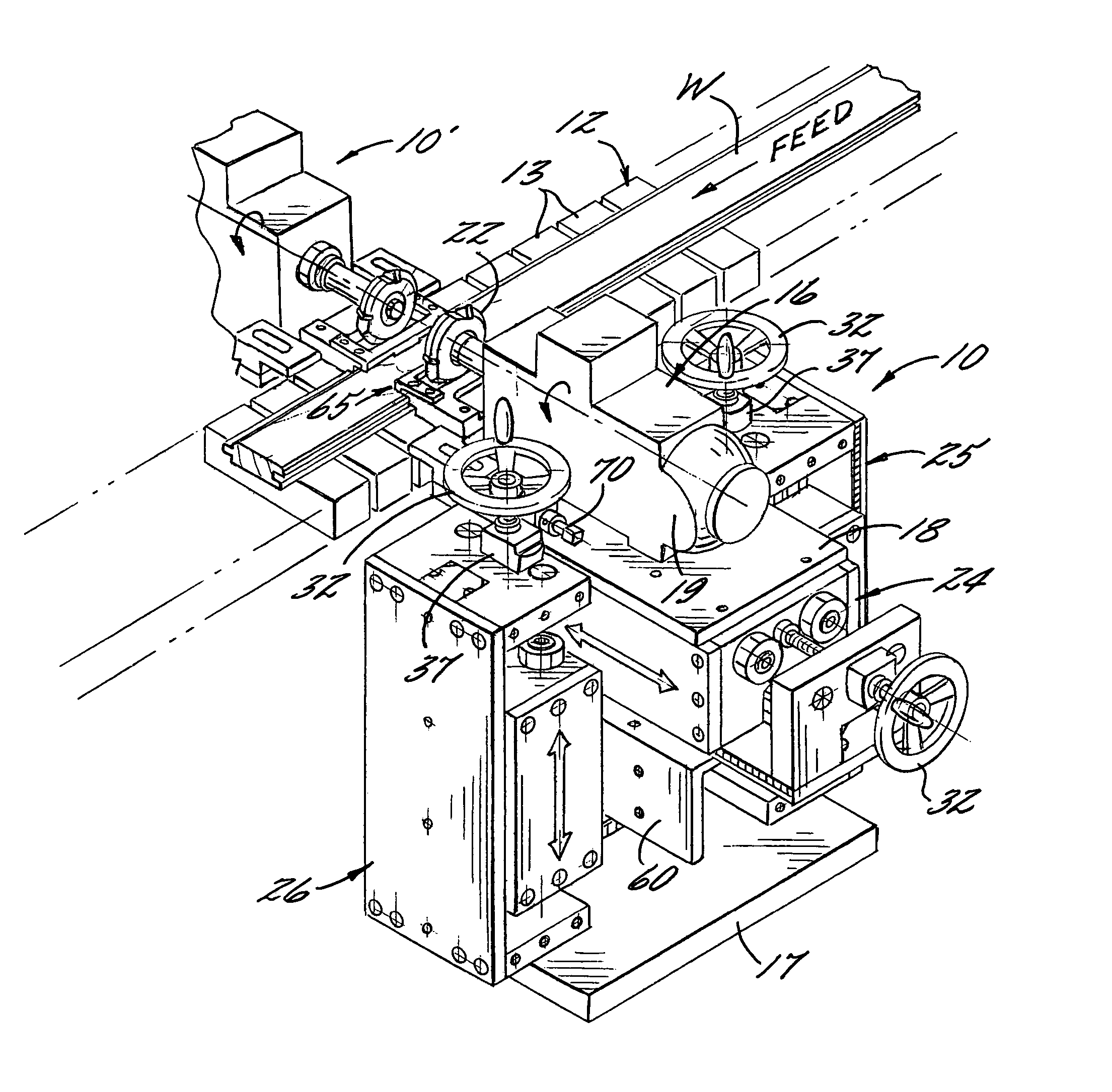
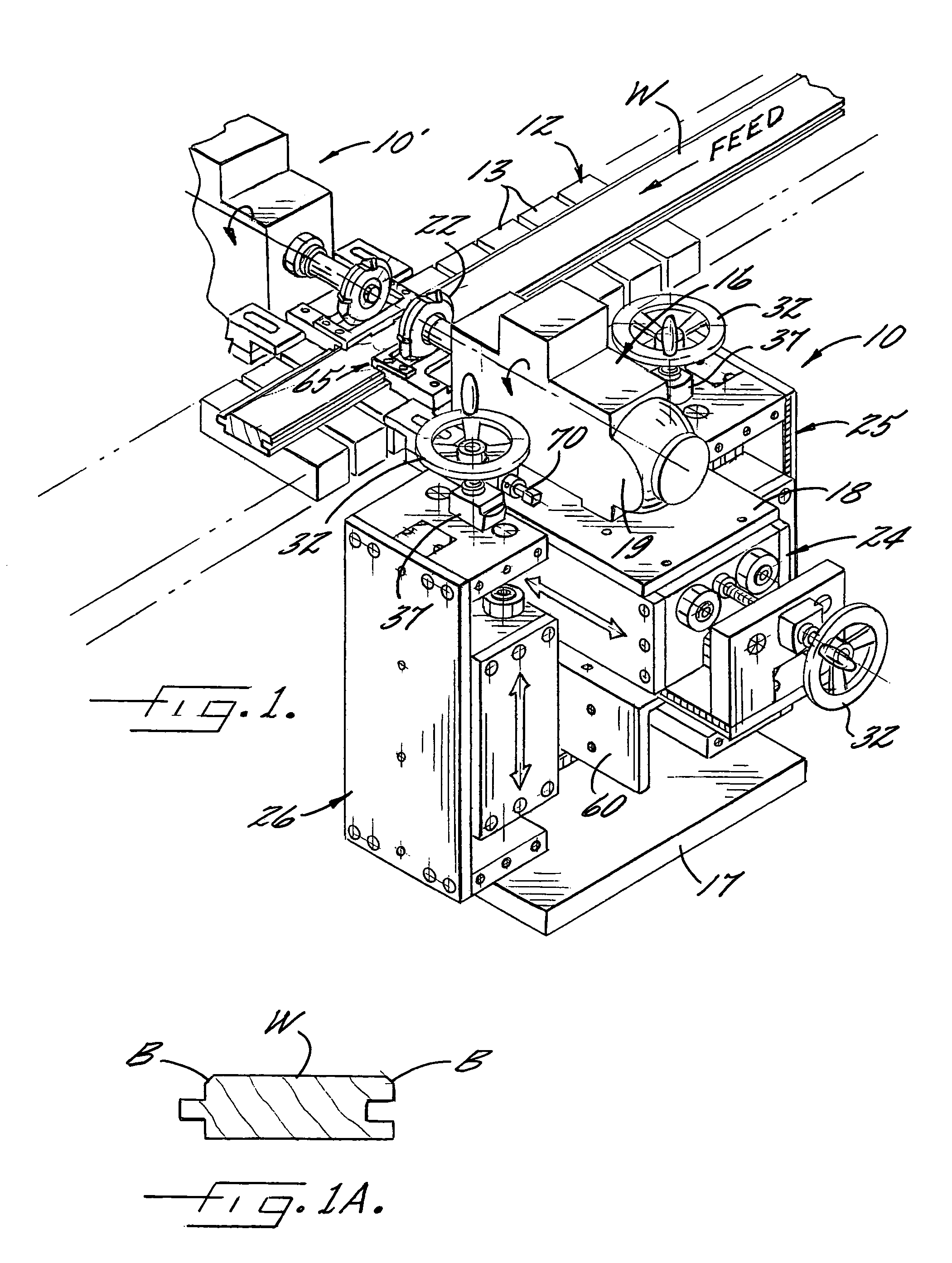
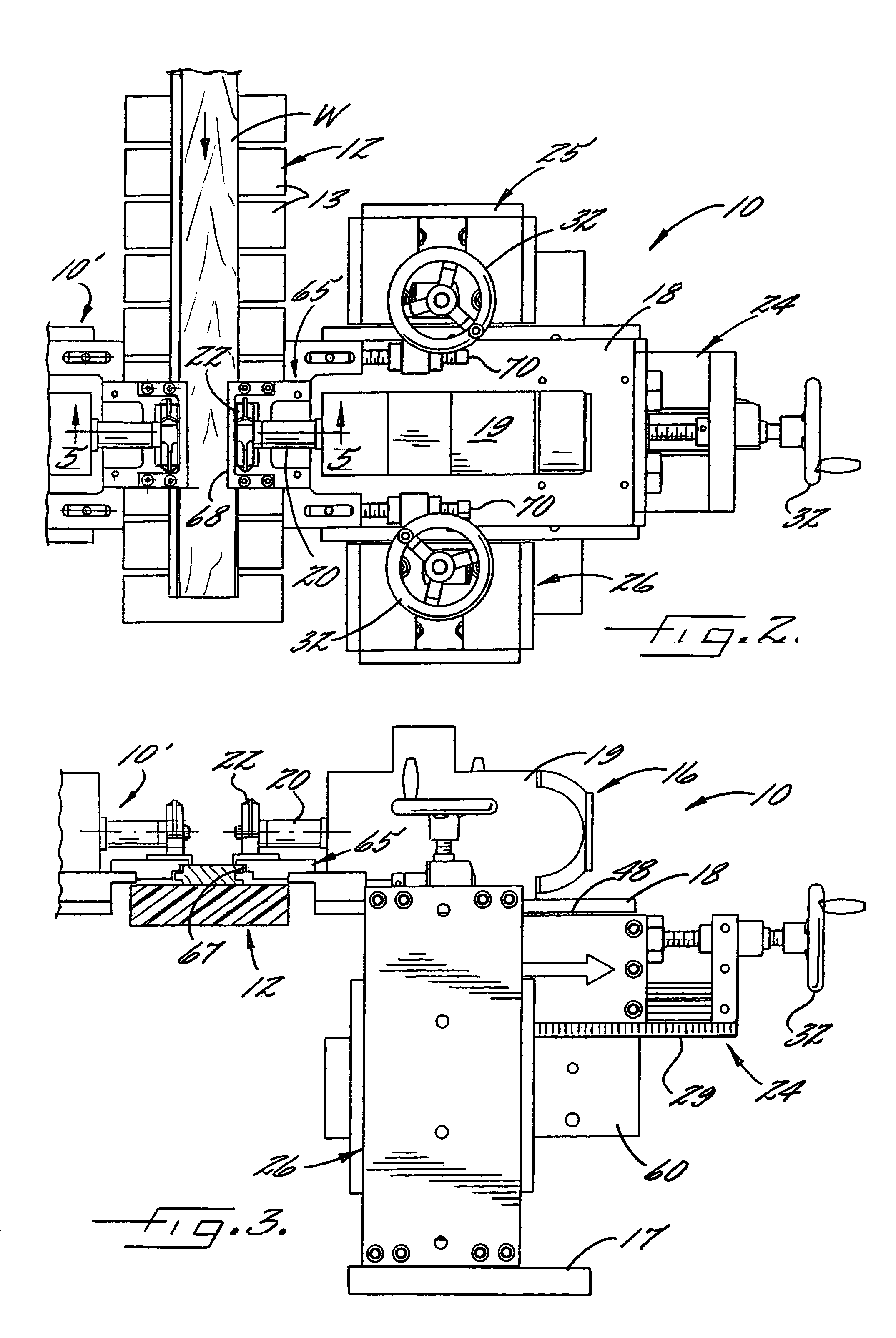
[0019]Referring more particularly to the drawings, a workpiece beveling apparatus 10 is illustrated which is positioned on one side of a conveyor 12 for serially advancing the workpieces W, which in this case are flooring strips having tongue and groove edges, along a horizontal linear path of travel. The conveyor 12 is conventional and is composed of a segmented belt 13 with hold down rollers 14, note FIG. 4.

[0020]The apparatus 10 is designed to cut a bevel B along one top edge of the advancing flooring strips as best seen in FIG. 1A, and when two apparatuses 10 and 10′ are utilized as further described below, a bevel may be simultaneously cut along both top edges.

[0021]The apparatus 10 comprises a motor assembly 16 mounted on a fixed frame 17 on one side of the conveyor 12, and the motor assembly 16 includes a horizontal support plate 18 which mounts an electric motor 19. The electric motor 19 has a drive shaft 20 which extends in a generally horizontal direction which is perpendi...


PUM

PropertyMeasurementUnit
spring biasing forceaaaaaaaaaa
dimensionsaaaaaaaaaa
thicknessaaaaaaaaaa

Abstract

An apparatus for beveling the edges of workpieces, such as flooring strips, as they are advanced along a path of travel on a conveyor. The apparatus has a motor assembly which mounts a cutting wheel, and the motor assembly is mounted for manual adjustment in both the in and out and up and down directions. Also, the motor assembly can float a limited distance in both of these directions. A guide shoe is mounted to the motor assembly and is positioned to ride on the workpieces. Any unevenness in the straightness, thickness, or width of the workpieces is detected by the guide shoe, which causes the motor assembly and thus the cutting wheel to closely follow the changing contour of the workpieces and impart a uniform bevel.

Description

BACKGROUND OF THE INVENTION[0001]The present invention relates to a beveling machine which is designed to cut a bevel of uniform dimensions along one or both edges of a workpiece, such as a floor strip with tongue and groove edges.[0002]Such flooring strips are not always of uniform straightness, thickness, and width, and when the individual strips are formed into a finished floor, there can be raised edges which can catch the heel of a person walking on the surface. To alleviate this problem, it has been conventional to cut a small bevel along each upper edge of the flooring strips, utilizing a cutting wheel which is mounted along each side of a conveyor which serially advances the flooring strips past the cutting wheels. However, this prior practice is not entirely satisfactory since the non-uniformity of the flooring strips results in a non-uniform bevel.[0003]It is accordingly an object of the present invention to provide a beveling machine which is adapted to cut a bevel along ...

Claims


Application Information

Patent Timeline
Patent Type & Authority Patents(United States)
IPC IPC(8): B23C3/00B23C1/04B23C3/12B27C5/02B27F1/02B27M3/04
CPCB27C5/02B27F1/02B27M3/04E04F15/02Y10T409/306496Y10T409/305264Y10T409/304144Y10T409/30532Y10T409/307168Y10T409/305208Y10T409/30392
Inventor BROOKS, LOUIS R.
Owner HASKO
Why Eureka
Try Eureka