Stacked SFP connector and cage assembly

a technology of connectors and cages, applied in the direction of coupling device details, coupling device connections, coupling protective earth/shielding arrangements, etc., can solve the problems of inability to meet the parameters of miniaturization, inability to provide space for spring-loaded doors and spring clips on the receptacle, and inability to meet the parameters of conventional pluggable module configurations

Active Publication Date: 2006-07-04
TYCO ELECTRONICS LOGISTICS AG (CH)
View PDF11 Cites 167 Cited by
  • Summary
  • Abstract
  • Description
  • Claims
  • Application Information

AI Technical Summary

Problems solved by technology

Although these conventional pluggable designs have been used successfully in the past, they tend to be unsuitable for miniaturization which is an ever-constant objective in the industry.
Conventional pluggable module configurations, however, cannot meet these parameters.
Miniaturizing a module while maintaining or even increasing its operating speed, presents a number of design problems particularly in applications in which data transmission rates are high, e.g., in the range of 1-10 Gbs (Gigabits / second).
Providing space for spring-loaded doors and spring clips on the receptacle tends to be problematic if not impossible in miniaturized configurations.
Additionally, the small size presents problems in dissipating heat from the module and incorporating traditional mechanisms for ejecting and retaining the module and for electrically connecting the module to the host circuit board.

Method used


Image

  • Stacked SFP connector and cage assembly
  • Stacked SFP connector and cage assembly
  • Stacked SFP connector and cage assembly

Examples


Embodiment Construction

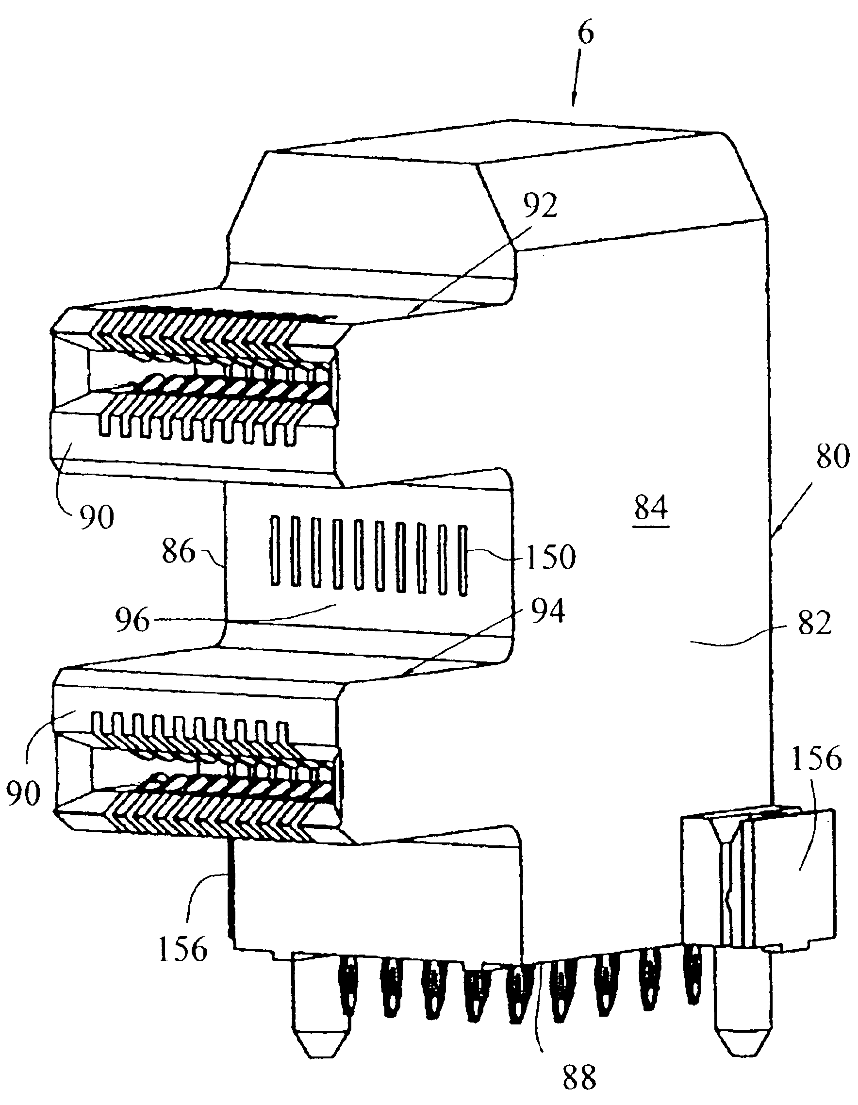
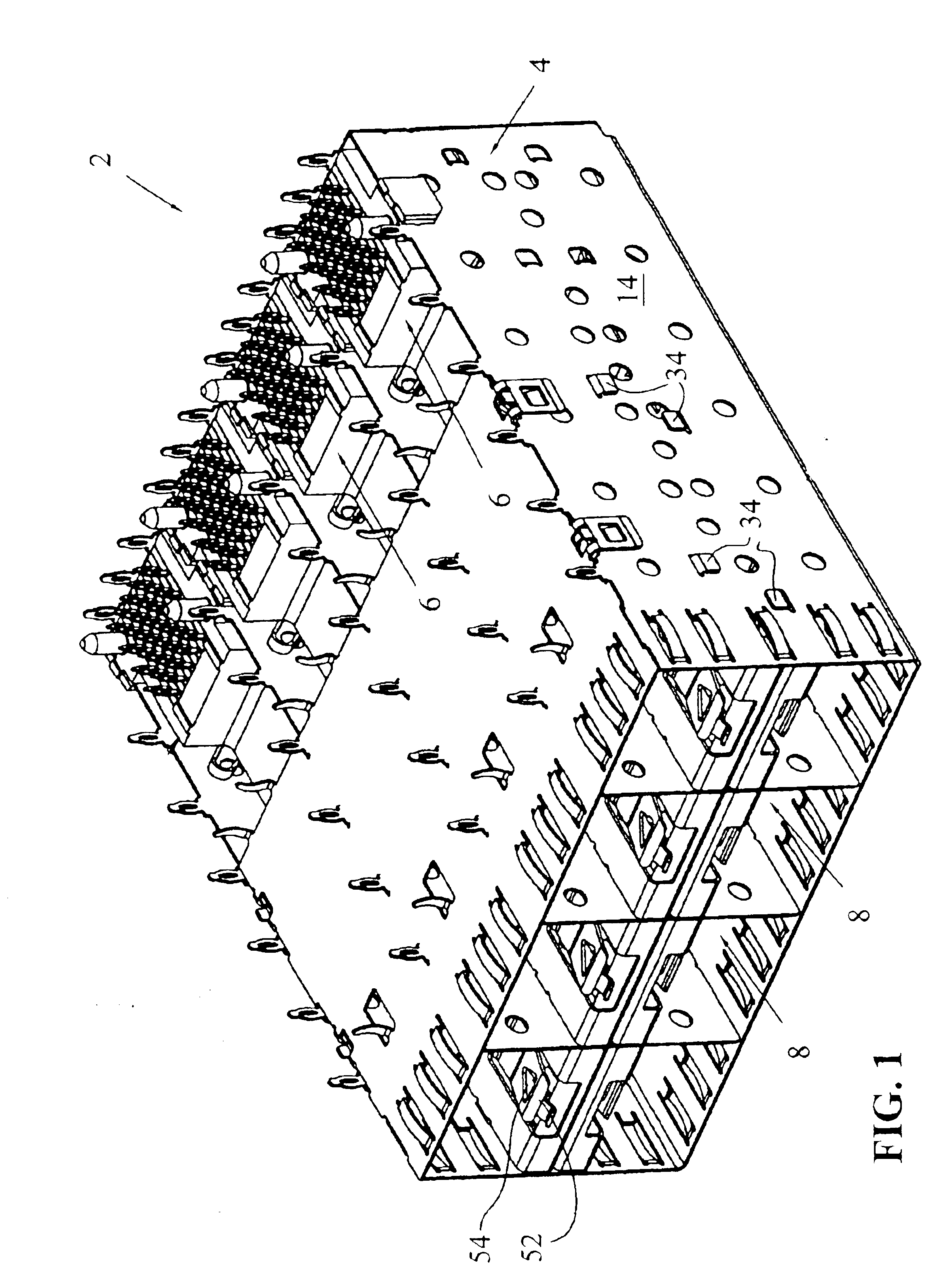
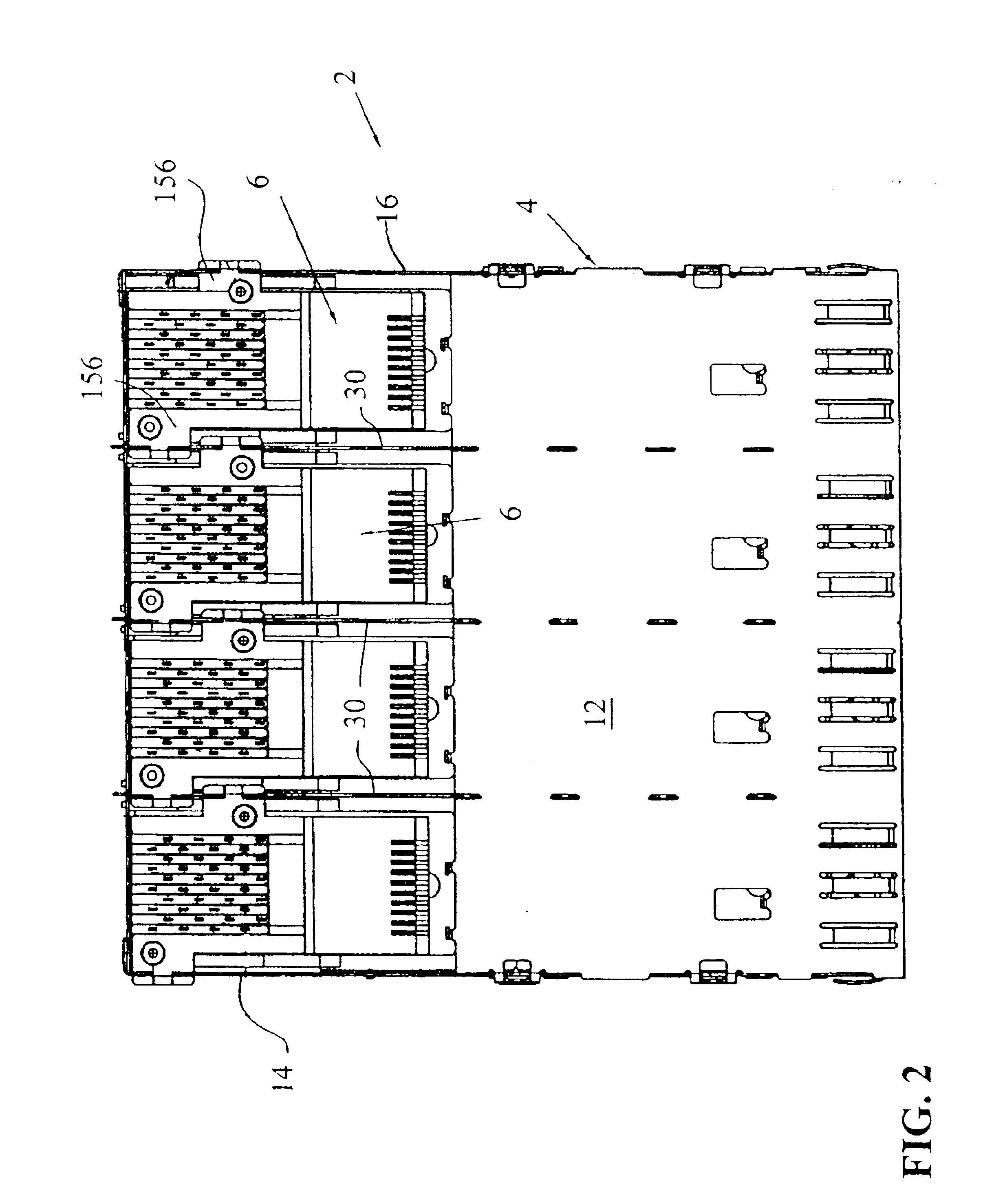
[0037]With reference first to FIGS. 1 and 2, an electrical connector assembly is shown generally at 2, which comprises a shielded, stamped and formed cage member 4 including a plurality of connector assemblies 6 positioned therein. It should be appreciated from FIG. 1 that the connector assembly is intended for placement on a motherboard and includes a plurality of ports 8 for receipt of modules, as will be described herein.

[0038]As shown in FIGS. 3 and 4, the cage member 4 is shown less the electrical connectors 6, and is shown generally comprised of a top wall 10, a lower wall 12, side walls 14 and 16, which together define the general enclosure for cage member 4. The cage member 4 is subdivided into rows by way of a center separator member 20, having a front face portion at 22 with an upper wall 24 (FIG. 3) and a lower wall 26 (FIG. 4). Meanwhile, the cage 4 is divided into columns by way of vertically extending divider walls at 30. It should be appreciated that the center separa...


PUM


Abstract

An electrical connector assembly is shown having a stamped and formed shielded cage having a plurality of ports for receiving SFP modules. The cages have an opening extending through a lower face thereof for receiving a header connector having first and second extensions which are aligned with the first and second columnar ports in the cage. Thus, the SFP modules are pluggable into individual ports, whereby two modules are interconnected to a single header connector interconnected to a motherboard.

Description

FIELD OF THE INVENTION[0001]The present invention relates generally to electronic connector systems and, more specifically, to low-profile connector systems for pluggable electronic modules, such as transceiver modules for high speed fiber optical and copper communications.BACKGROUND OF INVENTION[0002]It is known to provide a metal cage with a plurality of ports, whereby SFP modules are pluggable therein. Such modules are similar to that disclosed in U.S. Pat. No. 6,517,382. In fact, several pluggable module designs and standards have been introduced in which a pluggable module plugs into a receptacle which is electronically connected to a host circuit board. For example, a well-known type of transceiver developed by an industry consortium is known as a gigabit interface converter (GBIC) or serial optical converter (SOC) and provides an interface between a computer and a data communication network such as Ethernet or Fibre Channel. These standards offer a generally robust design whi...

Claims


Application Information

Patent Timeline
Patent Type & Authority Patents(United States)
IPC IPC(8): H01R13/60H01R12/16H01R13/514H01R13/658H05K9/00
CPCH01R13/65802H01R23/6873H05K9/0058H01R13/514H01R12/716H01R12/7064H01R2201/06H01R13/6582H01R13/6592H01R13/6594H01R13/6587H01R13/659H01R12/724
Inventor HENRY, RANDALL R.PHILLIPS, MICHAEL J.
Owner TYCO ELECTRONICS LOGISTICS AG (CH)
Why Eureka
Try Eureka