Design of beol patterns to reduce the stresses on structures below chip bondpads

a technology of beol pattern and structure, applied in the field of mechanical stress diversion under bondpad, can solve the problems of easy brittle or soft k materials, damage to low k dielectric materials, etc., and achieve the effect of increasing the effective usable area of the chip, and reducing the final chip siz

Inactive Publication Date: 2006-07-04
GLOBALFOUNDRIES INC
View PDF12 Cites 3 Cited by
  • Summary
  • Abstract
  • Description
  • Claims
  • Application Information

AI Technical Summary

Benefits of technology

[0012]The invention achieves several advantages, such as because the mechanical stresses are reduced in areas under the chip bondpad, the invention allows the semiconductor chip designer to include devices under the bondpad thereby increasing the effective usable area of the chip, which decreases the final chip size for a particular design. This significantly increases the number of chips per wafer, which consequently significantly reduces the manufacturing cost per chip. Furthermore, the ability to create structures to shield devices from excessive stresses in accordance with the invention allows the design of chips that are mechanically more robust than their traditional counterparts (when undergoing handling, probing, etc.). This allows for new possibilities for semiconductor applications that may require higher mechanical reliability. Moreover, the invention's approach to shield critical areas is not only applicable to shield active devices but can also be used to shield other features in a chip (critical metal line connections or vias, etc.).

Problems solved by technology

However, many low k materials are brittle or soft as compared to silicon dioxide and, when bonding forces are applied; the low k materials can be easily damaged.
More specifically, the forces applied during bonding processes (such as ultrasonic wirebonding) or during the formation of solderball (C4) connections, can damage the low k dielectric materials.
Thus, the damage from ultrasonic energy (wirebonding), capillary pressure and temperature can weaken or collapse the low k insulator.
Furthermore, the mechanical stresses associated with structures below the chip bondpads are such that a significant build up of these stresses may result in material failure, fatigue, and eventual device breakdown.

Method used


Image

  • Design of beol patterns to reduce the stresses on structures below chip bondpads
  • Design of beol patterns to reduce the stresses on structures below chip bondpads
  • Design of beol patterns to reduce the stresses on structures below chip bondpads

Examples


Embodiment Construction

[0028]The invention and the various features and advantageous details thereof are explained more fully with reference to the non-limiting embodiments that are illustrated in the accompanying drawings and detailed in the following description. It should be noted that the features illustrated in the drawings are not necessarily drawn to scale. Descriptions of well-known components and processing techniques are omitted so as to not unnecessarily obscure the invention. The examples used herein are intended merely to facilitate an understanding of ways in which the invention may be practiced and to further enable those of skill in the art to practice the invention. Accordingly, the examples should not be construed as limiting the scope of the invention.

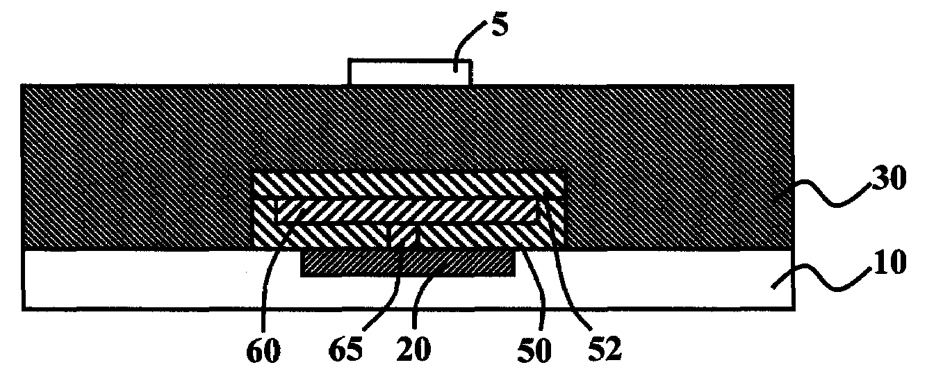
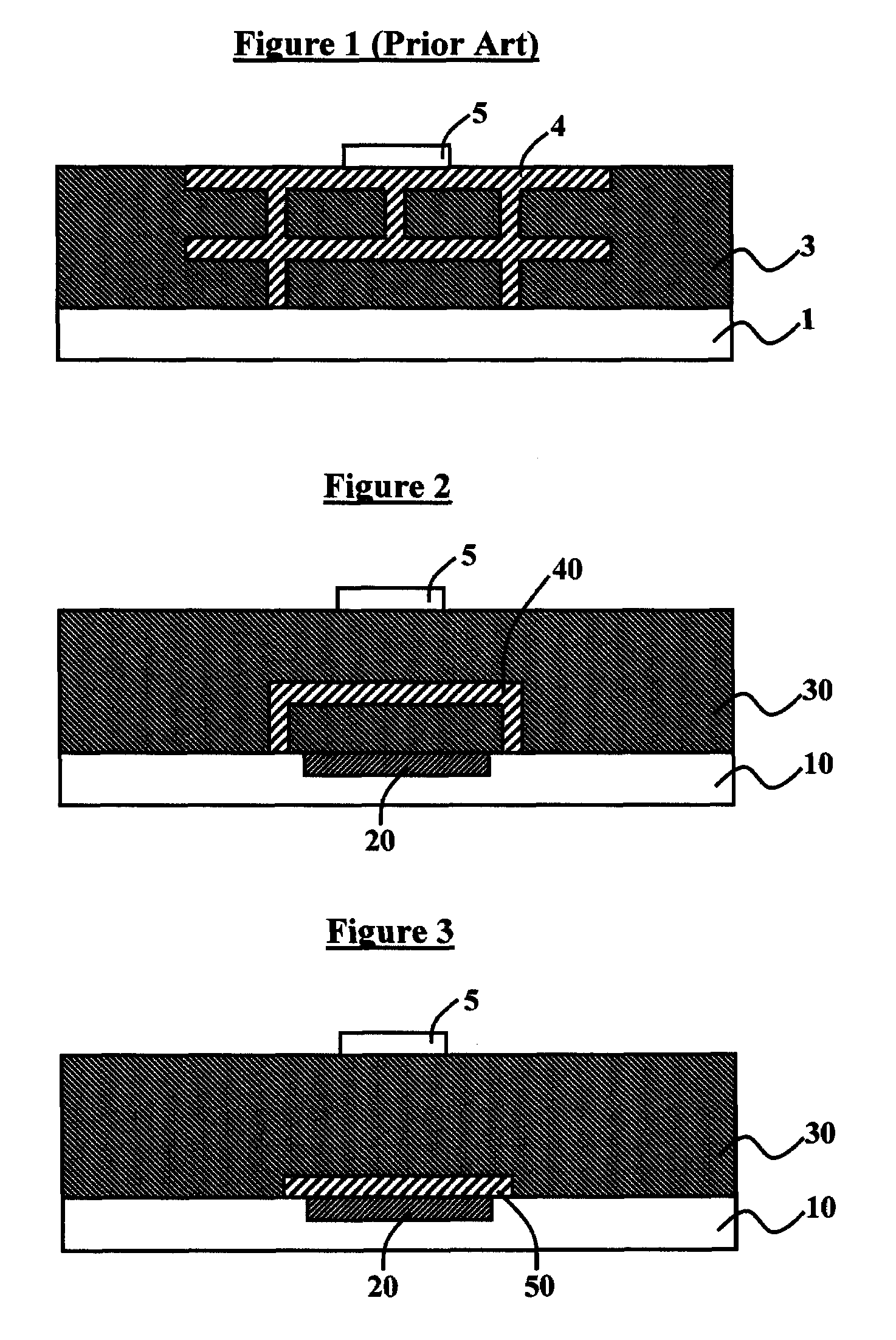
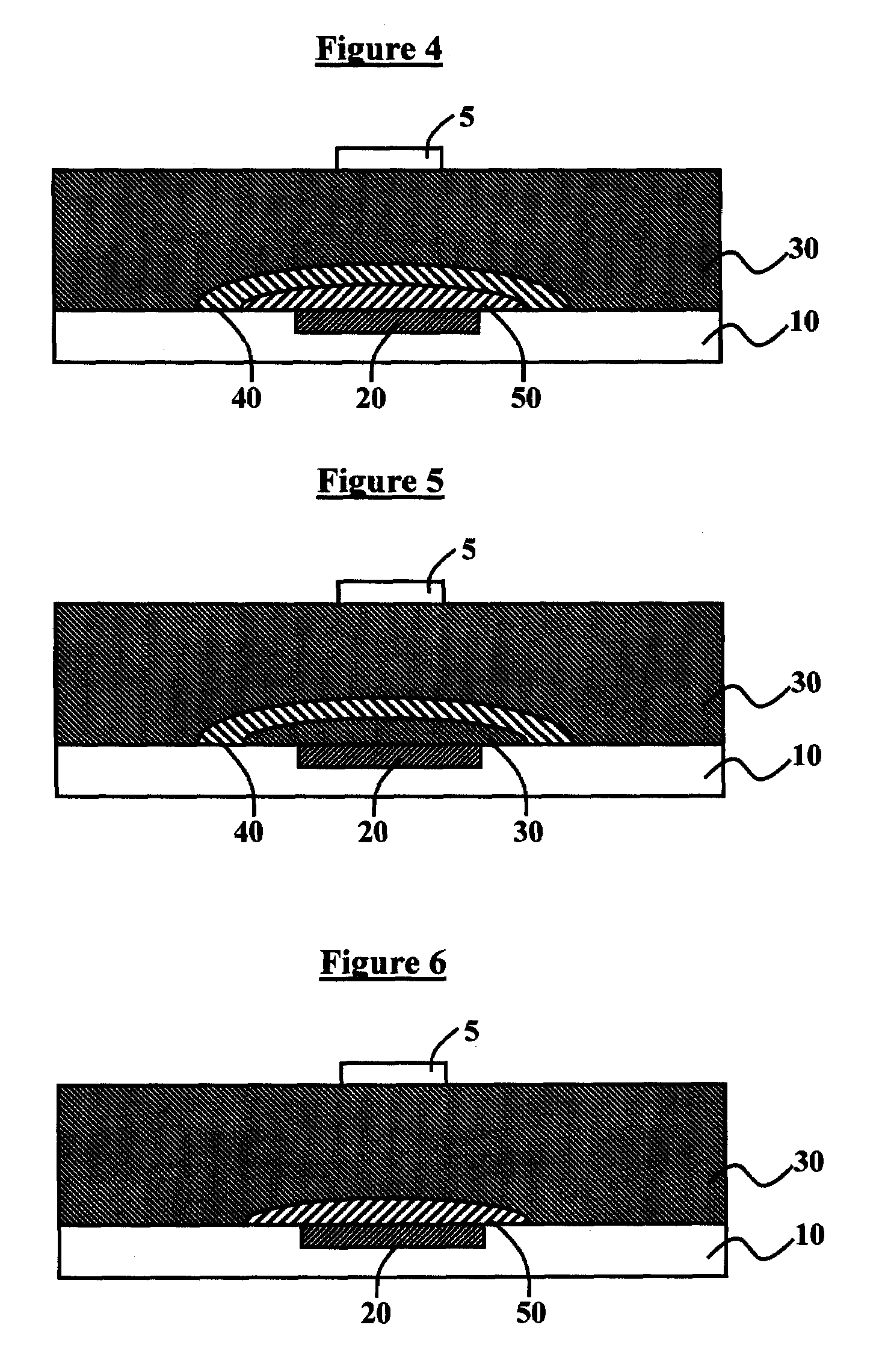
[0029]As previously mentioned, there is a need to shield active chip devices from mechanical stresses, especially below the chip bondpads, where significant forces are applied resulting in increased mechanical stresses in those areas. Refe...


PUM


Abstract

A semiconductor structure comprising a substrate including a first layer comprising a first material having a first modulus of elasticity; a first structure comprising a conductor and formed within the substrate, the first structure having an upper surface; and a stress diverting structure proximate the first structure and within the first layer, the stress diverting structure providing a low mechanical stress region at the upper surface of the first structure when a physical load is applied to the first structure, wherein said low mechanical stress region comprises stress values below the stress values in areas not protected by the stress diverting structure. The stress diverting structure comprises a second material having a second modulus of elasticity less than the first modulus of elasticity, the second material selectively formed over the upper surface of the first structure for diverting mechanical stress created by the physical load applied to the first structure.

Description

BACKGROUND OF INVENTION[0001]1. Field of the Invention[0002]The invention generally relates to semiconductor technologies, and more particularly to a mechanical stress diversion under bondpads on semiconductor chips.[0003]2. Description of the Related Art[0004]Conventional techniques for protecting structures on semiconductor chips include the approach described in U.S. Pat. No. 6,495,917 (hereinafter the '917 patent) issued to Ellis-Monaghan, et al. on Dec. 17, 2002, the complete disclosure of which is herein incorporated by referenced. As described in the '917 patent, the use of low dielectric potential (k) interlevel dielectric (ILD) materials (e.g., spin-on-glass (SOG), Hydrogensilsesquioxane (HSQ), Methylisilane (MSQ), Benzocyclobutene (BCB), etc.) has become very popular for input / output (I / O) and mechanical support structures which are applied to a previously fabricated semiconductor chip. Such I / O and support structures are formed after the logical function sections of the s...

Claims


Application Information

Patent Timeline
Patent Type & Authority Patents(United States)
IPC IPC(8): H01L23/48H01L23/52H01L29/40
CPCH01L23/562H01L24/02H01L2924/01013H01L2924/01014H01L2924/01033H01L2924/014H01L2924/14H01L2924/3025H01L2924/01019H01L2924/01029H01L2224/04042H01L24/05H01L2224/02125
Inventor AWAD, ELIEAWAD, MARIETTE A.FENG, KAI D.
Owner GLOBALFOUNDRIES INC
Why Eureka
Try Eureka