Fusible link unit

a technology of link unit and rattling sound, which is applied in the direction of electrical apparatus construction details, emergency protective devices, electrical apparatus, etc., can solve the problems of easy vibration, increase of manufacturing cost, and generation of rattling sound, so as to reduce assembly work efficiency, prevent rattling sound, and increase manufacturing cost

Active Publication Date: 2006-07-04
YAZAKI CORP
View PDF9 Cites 31 Cited by
  • Summary
  • Abstract
  • Description
  • Claims
  • Application Information

AI Technical Summary

Benefits of technology

[0014]Accordingly, an object of the present invention is to provide a fusible link unit which prevents the screw fixing terminal portions that are not in use from

Problems solved by technology

In its raised state, it easily vibrates when it receives a vibration from outside, and generates rattling sounds.
Howev

Method used


Image

  • Fusible link unit
  • Fusible link unit
  • Fusible link unit

Examples


Embodiment Construction

[0034]The preferred embodiment of the present invention will be described with reference to the accompanying drawings.

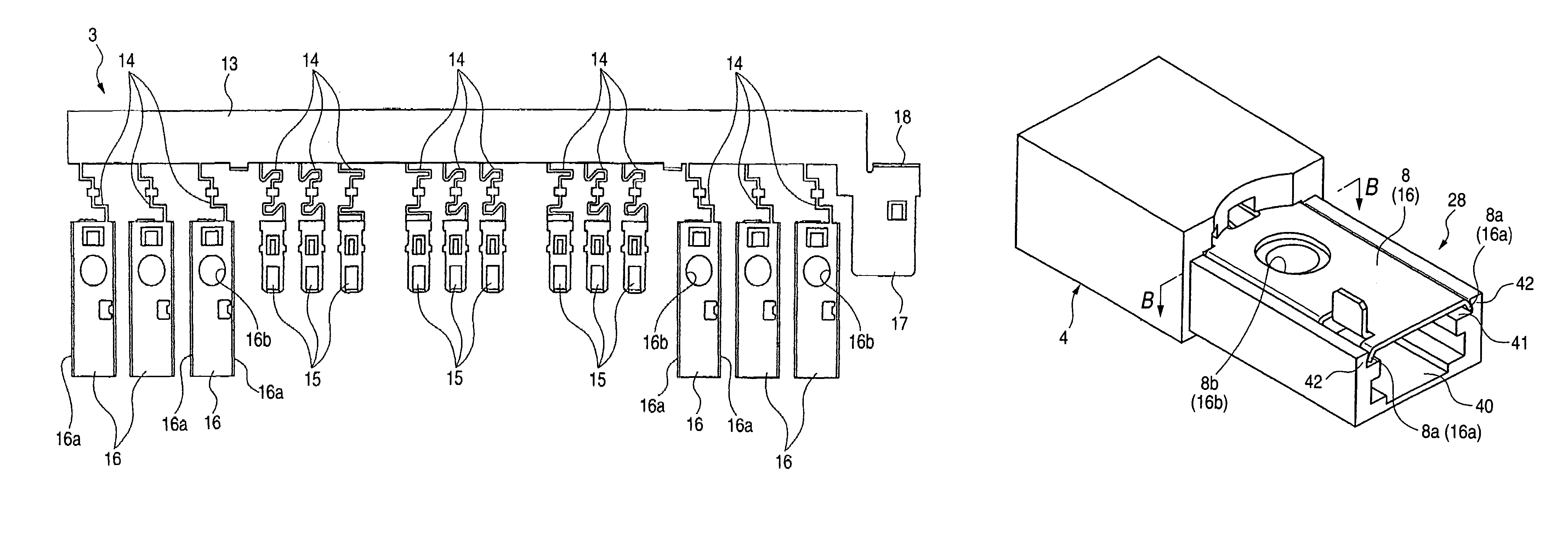
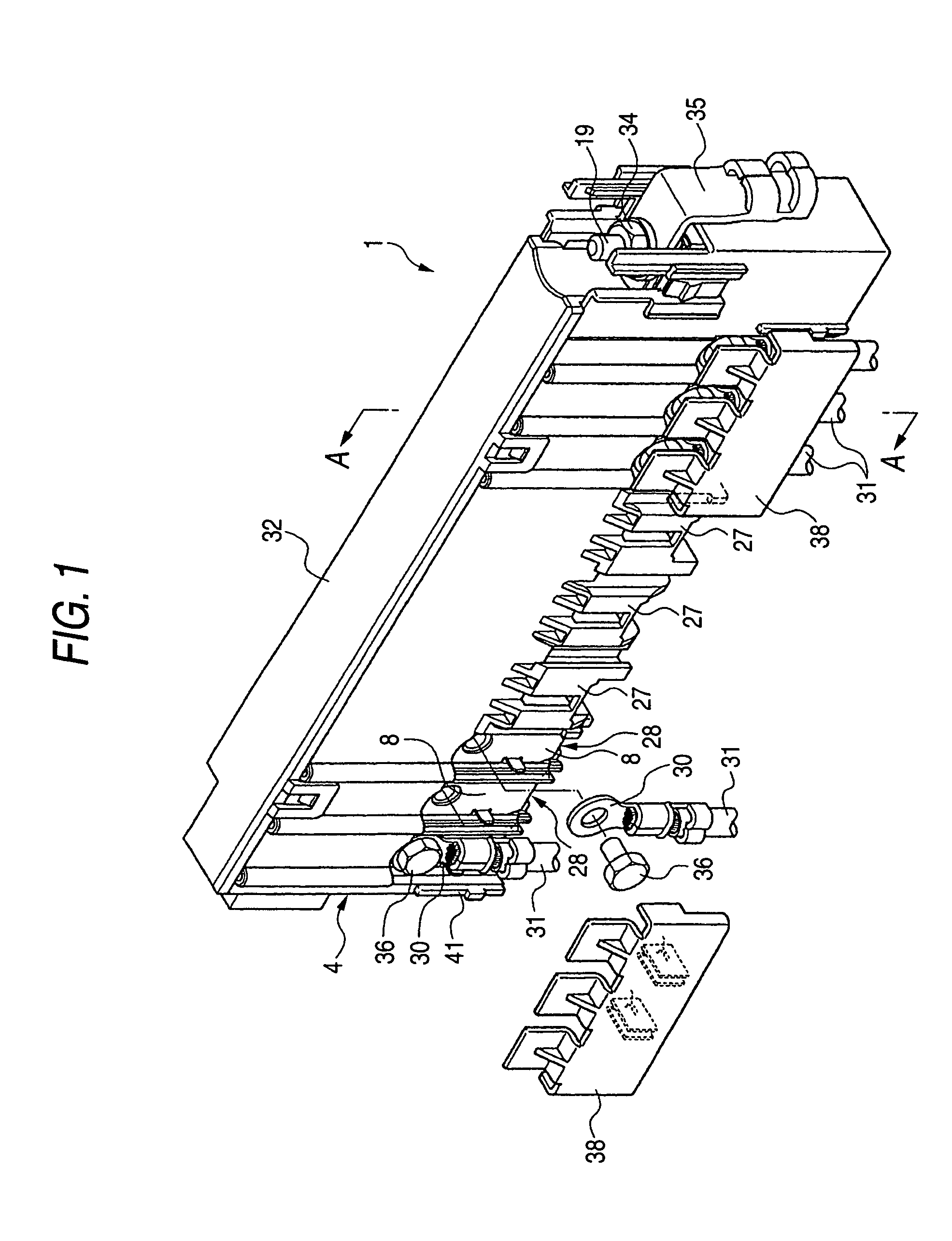
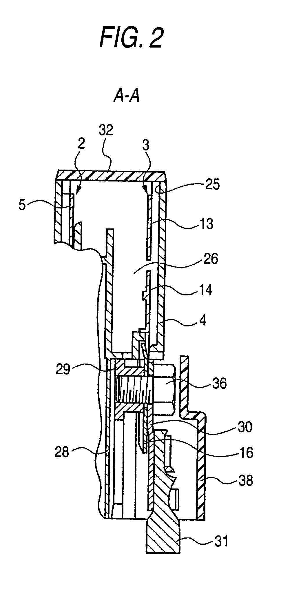
[0035]FIGS. 1 through 8B show the preferred embodiment of the present invention. Of those figures, FIG. 1 is a perspective view showing a fusible link unit. FIG. 2 is a cross sectional view taken on line A—A in FIG. 1. FIG. 3 is a bottom view showing terminal supports juxtaposed with each other. FIG. 4 is a front view showing a first fuse circuit structure. FIG. 5 is a front view showing a second fuse circuit structure. FIG. 6A is a perspective view showing the terminal support. FIG. 6B is a bottom view showing the terminal support. FIG. 7A is an exploded view taken on line B—B in FIG. 6A. FIG. 7B is a cross sectional view taken on line B—B in FIG. 6A. FIG. 8A is a bottom view showing a screw fixing terminal portion in each of the first and second fuse circuit structures. FIG. 8B is a bottom view showing a terminal support of a housing.

[0036]As shown in FIGS. 1 throu...


PUM


Abstract

Disclosed is a fusible link unit having a fuse circuit structure containing screw fixing terminal portions linked through fusible members to a linking plate, and a housing into which the first fuse circuit structure is assembled, wherein a plurality of terminal supports for supporting the screw fixing terminal portions in a state that the front surfaces of the screw fixing terminal portions are exposed to outside are provided in the housing. The fusible link unit is improved in that the terminal supports of the housing each include pawl parts for preventing each screw fixing terminal portion from displacing to a surface thereof.

Description

[0001]The present application is based on Japanese Patent Application No. 2002-289716, the entire contents of which are incorporated herein by reference.BACKGROUND OF THE INVENTION[0002]1. Field of the Invention[0003]The present invention relates to a fusible link unit with fuse circuit structures each containing terminal portions connected with fusible members, wherein the terminal portions are linked like a chain.[0004]2. Related Art[0005]The fusible link units of this type are generally known. (See Japanese Patent Publication No. JP-A-2000-133114, for example). FIGS. 9 through 13B shows one of such the fusible link units. The fusible link unit designated by reference numeral 100, as shown in FIGS. 9 and 10, is generally composed of first and second fuse circuit structures 101 and 102 and a housing 103 into which those fuse circuit structures 101 and 102 a reassembled. The first fuse circuit structure 101, as illustrated in detail in FIG. 11, is made up of a linking plate 104, a p...

Claims


Application Information

Patent Timeline
IPC IPC(8): H01H85/20H01H85/175H01H85/12H01H85/044
CPCH01H85/044H01H85/2045H01H2085/0555
Inventor NAKAMURA, GORO
Owner YAZAKI CORP
Why Eureka
Try Eureka