

Touch panel and an input device equipped therewith
a technology of input device and touch panel, which is applied in the field of touch panel and input device, can solve the problem of reducing the operation of fluorescent light reflection inside, and achieve the effect of small heat contraction rate and small water absorption ra
- Summary
- Abstract
- Description
- Claims
- Application Information
AI Technical Summary
Benefits of technology
Problems solved by technology
Method used
Image

Examples
first embodiment
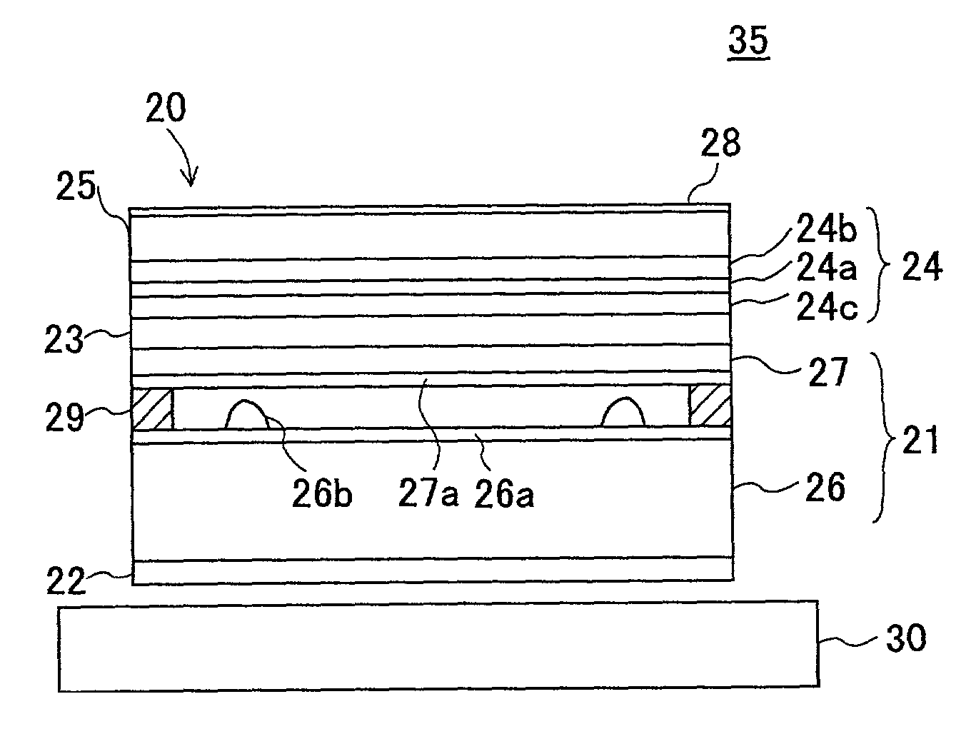
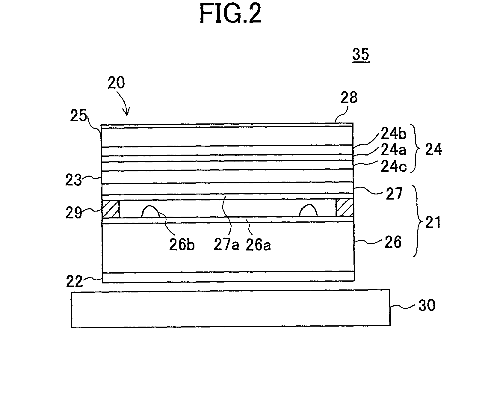
[0042]FIG. 2 shows a touch panel 20 of the present invention. The touch panel 20 is formed on the upper surface of a liquid crystal display 30. The liquid crystal display 30 and the touch panel 20 are components of an input device 35.
[0043]The touch panel 20 includes a λ / 4 phase-difference film 22 pasted on the back of a touch panel main part 21 in order to suppress light reflection, another λ / 4 phase-difference film 23 and a polarizing plate 24 pasted on the upper surface of the main part 21 of the touch panel in order to suppress light reflection, and a polyethylene naphthalate (PEN) film 25 pasted on the surface of the polarizing plate 24 in order to enhance resistance to high temperature and humidity.
[0044]Absorption axes of the λ / 4 phase-difference film 22, the λ / 4 phase-difference film 23, and the polarizing plate 24 have relations as shown in FIG. 3. An absorption axis 24a of the polarizing plate 24 and an absorption axis 30a of the liquid crystal display 30 are the same at 4...
second embodiment
[0135]A touch panel 100 of the present invention is shown in FIG. 8. The touch panel 100 is formed on the upper surface of a liquid crystal display 30. The touch panel 100 and the liquid crystal display 30 are components of an input device 110.
[0136]The touch panel 100 is configured with a polarizing plate that has an enhanced resistance to heat and humidity. In FIG. 8, components that are the same as shown in FIG. 2 are referenced by the same reference numbers.
[0137]The touch panel 100 includes the touch panel main part 21, under the lower surface of which the λ / 4 phase-difference film 22 is pasted in order to suppress the reflected light, and on the upper surface of the touch panel main part 21, the λ / 4 phase-difference film 23 and a polarizing plate 101 are pasted in order to suppress the reflected light.
[0138]The polarizing plate 101 includes the extended film (polarizing film) 24a of polyvinyl alcoholic film with dye mixed and extended, and films 101b and 101c of polycycloolefi...
third embodiment
[0157]A touch panel 150 of the present invention is shown in FIG. 10. The touch panel 150 is formed on the upper surface of the liquid crystal display 30. The touch panel 150 and the liquid crystal display 30 are components of an input device 160.
[0158]The touch panel 150 includes a film of fluororesin 151 on the upper surface of the polarizing plate 24, which is provided aiming at improvement in resistance to heat and humidity. In FIG. 10, components that are the same as in FIG. 2 are referenced by the same reference numbers.
[0159]The third embodiment provides a fluororesin film 151 that has a thickness of about 50 micrometers. The fluororesin is formed by applying a fluorine surface treatment agent to the upper surface of the polarizing plate 24, a fluororesin coating, and then, dry-hardening.
[0160]An evaluation result of the touch panel 150 is as follows.
[0161]The total light reflection factor was 1.5%. Further, the high temperature storing examination and the high humidity stori...
PUM
 Abstract
Description
Claims
Application Information