Telephony end user interface in an HFC access network

a technology of end user interface and telephony, which is applied in the direction of time-division multiplexing selection, error detection/correction, instruments, etc., can solve the problems of inability to provide backup power, drawbacks of conventional status indicators used for this purpose, and use of remote network devices

Inactive Publication Date: 2006-07-04
ARRIS ENTERPRISES LLC
View PDF8 Cites 51 Cited by
  • Summary
  • Abstract
  • Description
  • Claims
  • Application Information

AI Technical Summary

Problems solved by technology

Various problems can occur with the supply of power to a remote access device, such as an EMTA, which includes failure of the commercial utility alternating current source providing power to the subscriber's premises.
Backup power supplies such as backup batteries, however, typically are only able to provide backup power, after failure of the main power supply, for temporary periods of time until their storage of power has been depleted.
The conventional status indicators used for this purpose have drawbacks.
Users have been subject to losing the use of remote network devices during main power failure events without any suitable advance warning, an occurrence which often leads to lost work and productivity.
Unfortunately, the access device and its backup power source are often not located within the premises at the same location where a user is operating a communication device (e.g., a POTS phone, an integrated services digital network (ISDN) phone, and so forth).
This problem is aggravated when the subscriber premises network provides multiple extensions for connecting user devices in different rooms at the same time.
As a consequence, the backup power indicator or low backup power indicators often have been hidden or obscured from view from the user or subscriber in previous arrangements.
In these prior arrangements, the end user often did not have any indication that the main power had been lost (and thus the backup power was on), or that the backup power may be approaching the end of its capacity.

Method used


Image

  • Telephony end user interface in an HFC access network
  • Telephony end user interface in an HFC access network
  • Telephony end user interface in an HFC access network

Examples


Embodiment Construction

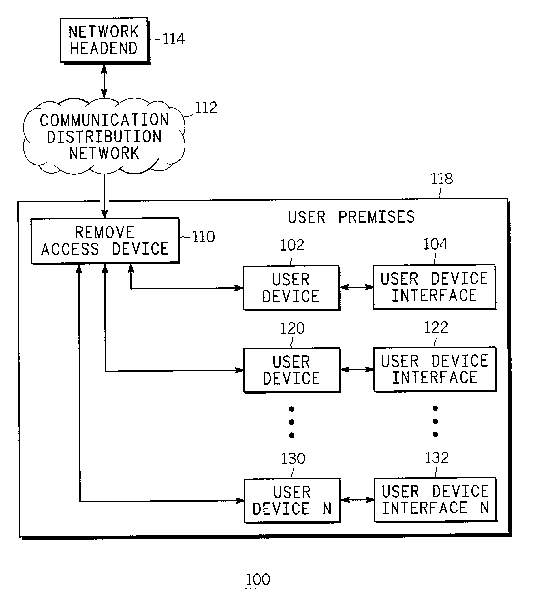
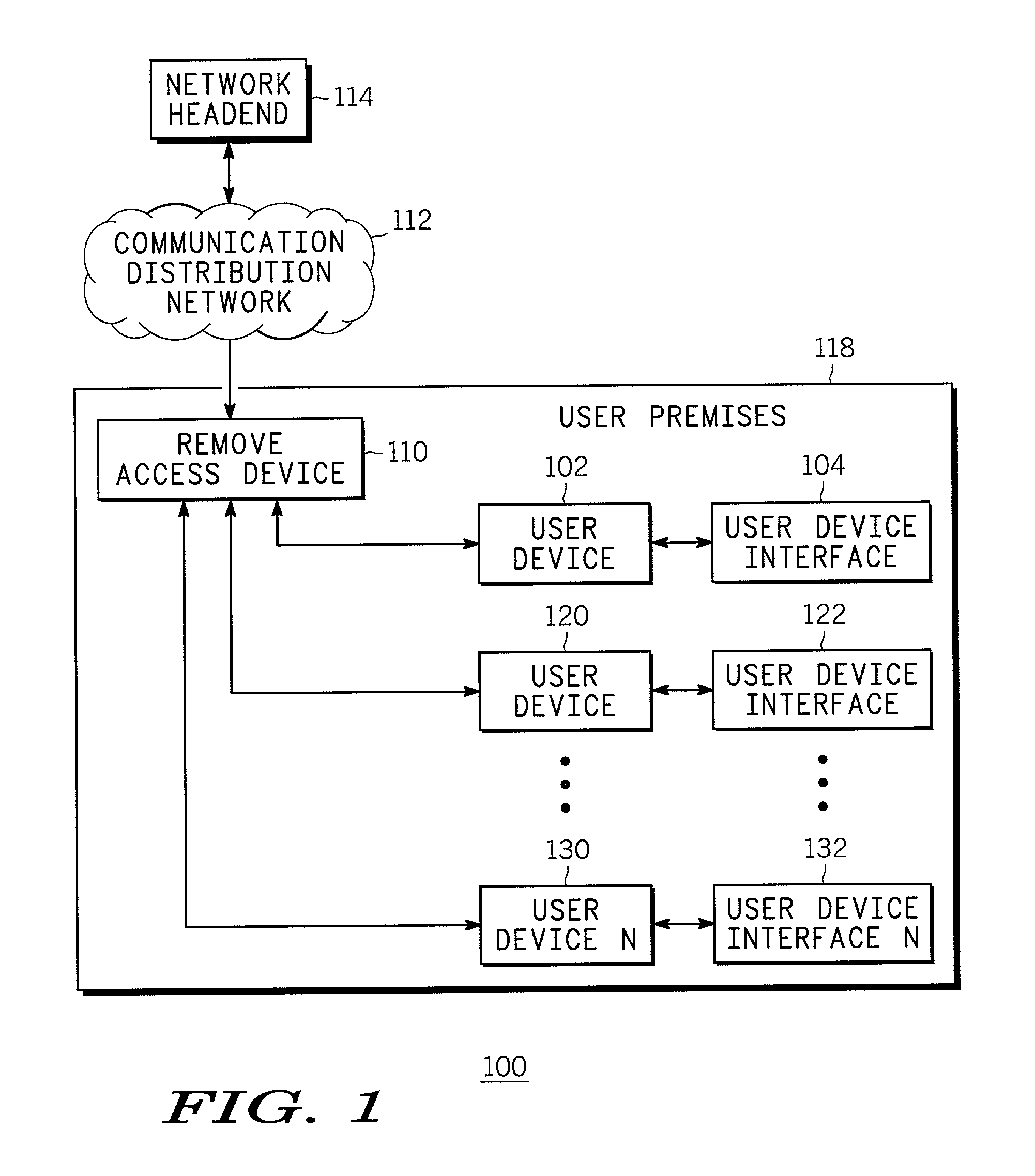
[0011]Regarding FIG. 1, a communications system 100 is shown having a user premises network 118 in which multiple user devices 102, 120, 130, and so forth are accessing a remote access device 110. The access device110 is coupled to a communication distribution network 112. Additionally, a network headend 114 is coupled to the communications distribution network 112. Remote access device 110 can interact with, and be monitored and controlled by, the network headend 114. In an embodiment, network headend 114 includes an operations and maintenance center (OMC) for control, monitoring, and maintenance of the remote access device 110.

[0012]A single user or subscriber premises network 118 is shown to simplify discussion. It will be understood that the communications system 100 typically will have multiple subscriber premises networks coupled into the system. Further to this embodiment, the user premises network 118 is premise powered, such as by commercial AC utility power fed onto the us...


PUM


Abstract

System (100) and method for providing power supply status indications and network-originated messages on a user device interface (104) of a user device (102) coupled to an access device (110). The access device (110) receives a supply of main power from a main power supply (204), and the access device (110) is adapted to interface with a communications network (111). A backup power supply (206) is coupled to the access device (110) and is adapted to supply backup power to the access device (110) when the supply of main power (214) fails. The backup power supply (206) provides a signal indicating a power condition of the backup power supply (206) when the supply of main power (214) fails. A processor unit (208) receives the signal and generates a backup power supply status indication in response to the signal. At least one user device (102) is coupled to the access device (110) and also is adapted to receive and / or transmit information over the communications network (111) via the access unit (110). The user device (102) receives the backup power supply status indication and the status indication is communicated to a user through a user device interface (104) coupled to the user device (102).

Description

BACKGROUND OF THE INVENTION[0001]1. Field of the Invention[0002]The present invention generally relates to providing status messages in networks, and more particularly to user notification at end user devices of remote backup power supply indications and subscription service messages.[0003]2. Background of the Invention[0004]Wired access communication networks link multiple remote access devices for delivery of one or more of telephony, data, video programming or other broadband services to end user devices. Commercial utility alternating current (AC) is commonly used to provide a source of power for the remote access devices wired into networks. In a VoIP EMTA (voice-over-Internet protocol embedded-media-terminal-adaptor) communication system, for example, an embedded media terminal adaptor (EMTA) is a broadband telephony interface used to deliver broadband Internet, data, and / or voice access jointly with telephony service to a subscriber's or customer's premises using a cable netw...

Claims


Application Information

Patent Timeline
Patent Type & Authority Patents(United States)
IPC IPC(8): G06F9/445H04M11/00H04Q11/04
CPCH04Q11/0471H04Q2213/13389H04Q2213/13031H04Q2213/13034H04Q2213/1308H04Q2213/13093H04Q2213/13096H04Q2213/13106H04Q2213/13166H04Q2213/13167H04Q2213/13175H04Q2213/13202H04Q2213/13209H04Q2213/13292H04Q2213/1332H04Q2213/13012
Inventor FREYMAN, PHILLIP KENTADY, ROGER WILLIAM
Owner ARRIS ENTERPRISES LLC
Why Eureka
Try Eureka