
Eyebrow comb attachment for hair clipper

Inactive Publication Date: 2006-07-11
WAHL CLIPPER
View PDF10 Cites 11 Cited by
  • Summary
  • Abstract
  • Description
  • Claims
  • Application Information

AI Technical Summary

Benefits of technology

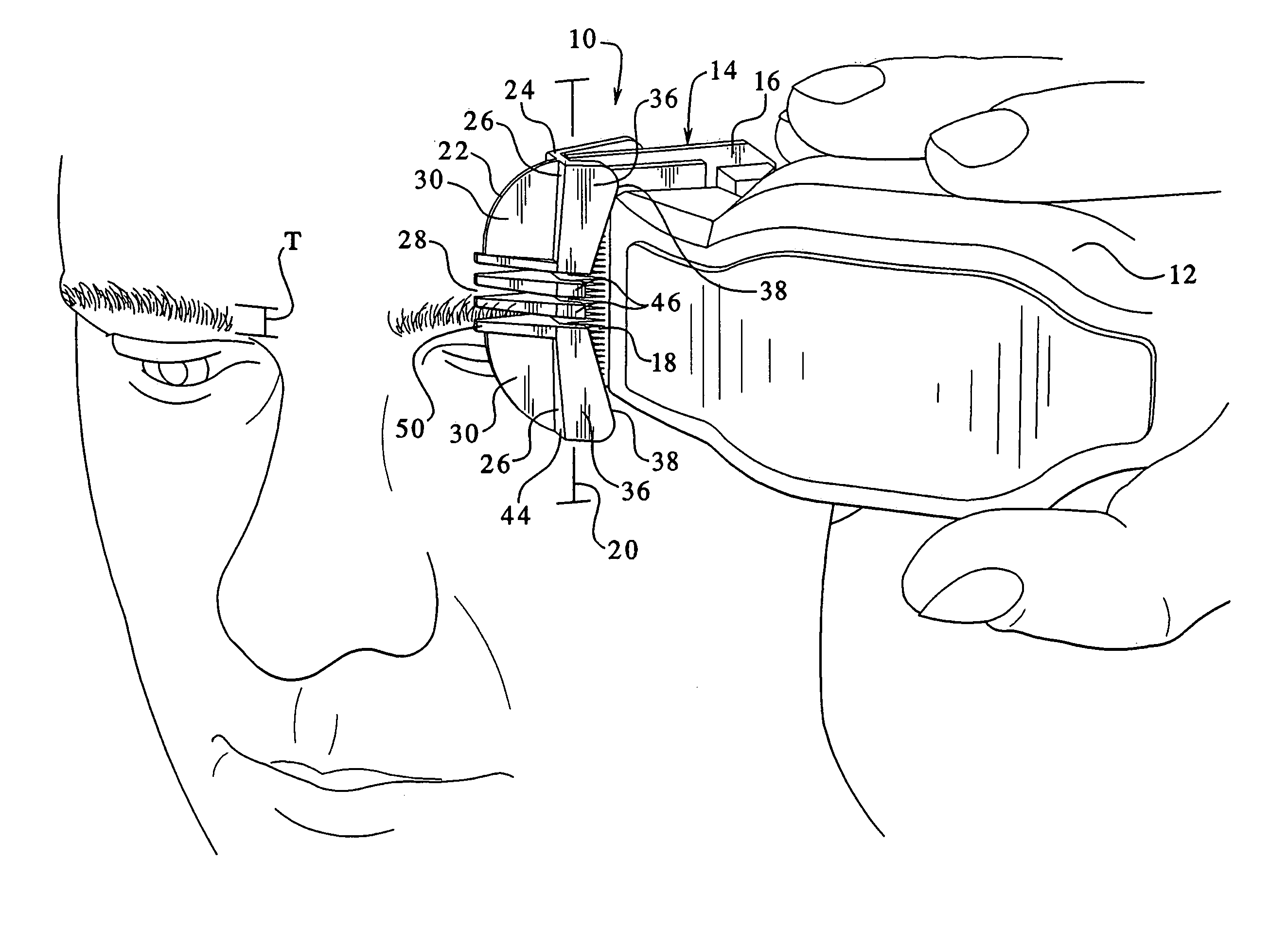
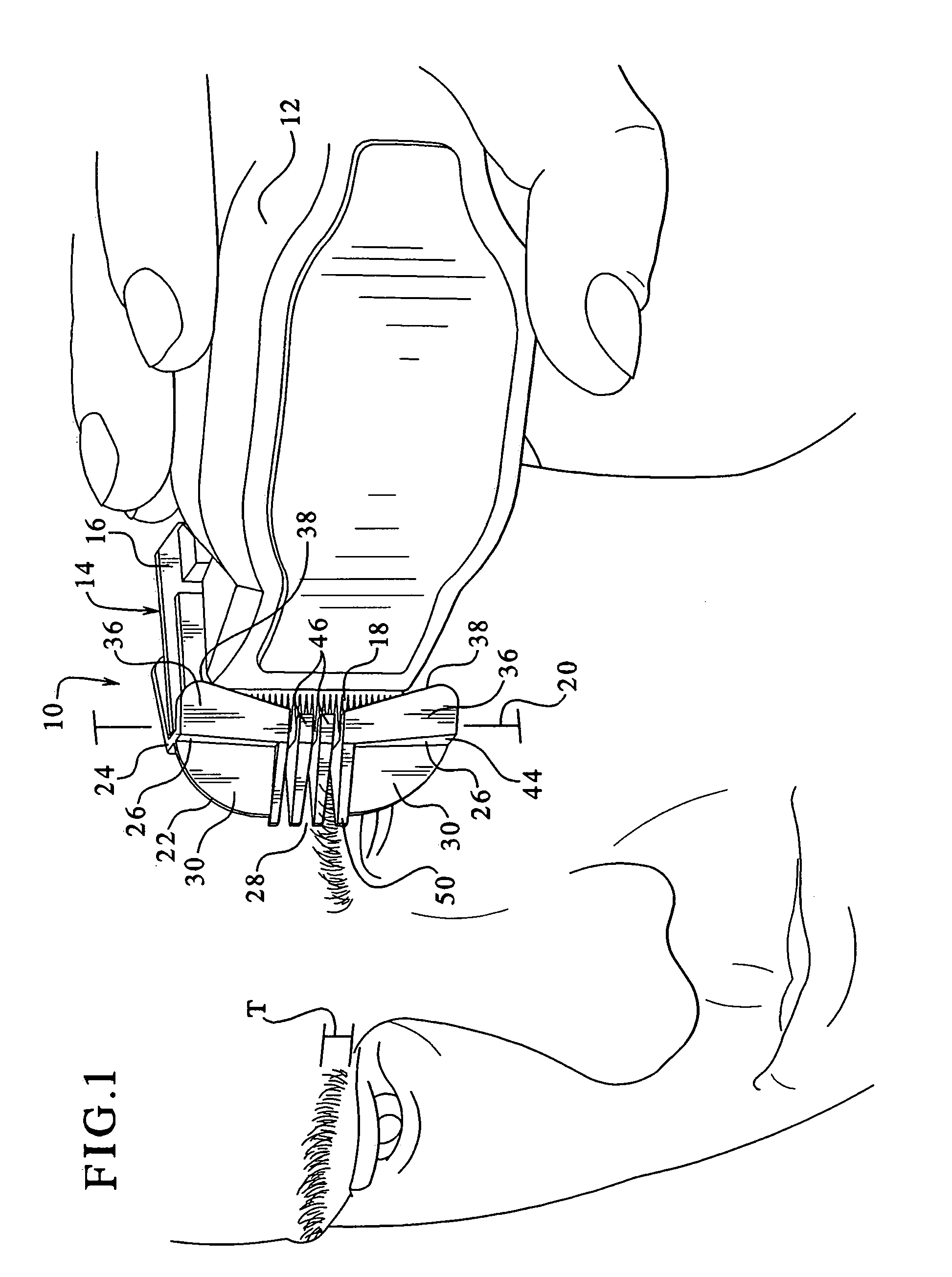
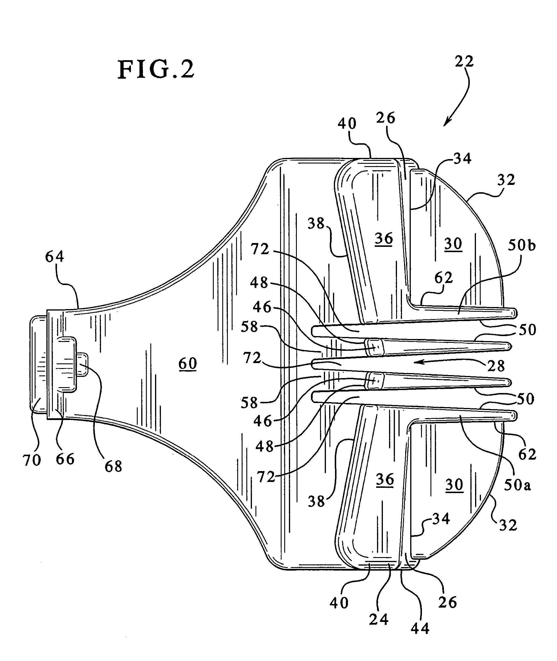
[0006]The above-identified needs are addressed by the present eyebrow comb attachment for a hair clipper, which is removably attachable to a conventional hair trimmer or hair clipper blade end. The attachment of the present device is similar to that of a conventional attachment comb. One feature of the present attachment is a blade guard for obscuring, masking or blocking much of the width of the cutting edge of the conventional clipper blade, and revealing only a relatively small cutting area of the blades for access to the eyebrow area. In this manner, the user's eyes are protected from the moving clipper blades. Another feature of the present eyebrow attachment is that deflecting surfaces are provided for helping prevent hair clippings from entering the eye. Still another feature of the present eyebrow comb attachment is the provision of comb teeth for guiding eyebrow hair into the relatively narrow, unobscured or exposed cutting area where the blades are available for cutting.

Problems solved by technology

However, one drawback to the use of a power trimmer around the eyes is that the clippings generated in the trimming process can become caught in the eye and be irritating to the user.
Another drawback of using powered trimmers for eyebrow trimming is that the trimmer itself must be located in relatively close proximity to the eye.
While it is known to use conventional trimmers or clippers having attachment combs for trimming eyebrow hair, one disadvantage of that application is that the relatively wide cutting blade of such devices risks cutting any hair of the normal head hair which happens to be on the forehead or in close proximity to the eyebrow area.
Another drawback of using conventional hair trimmers with combs for eyebrow trimming is that the relatively wider blade inherently entails comb teeth which typically extend the full width of the blade, which may come in close proximity to the eye.

Method used


Image

  • Eyebrow comb attachment for hair clipper
  • Eyebrow comb attachment for hair clipper
  • Eyebrow comb attachment for hair clipper

Examples


Embodiment Construction

[0013]Referring now to FIG. 1, a powered hair clipper or hair trimmer (here used interchangeably) suitable for use with the present attachment is generally designated 10. Included on the clipper 10 is a housing 12 enclosing a power source (not shown) preferably an electric motor, powered by line voltage or batteries as is well known in the art. While a powered hair clipper 10 is depicted, it is contemplated that the present attachment is usable on manually operated clippers as are known in the art. One end of the housing 12 is the mounting point for a bladeset 14 formed by a stationary blade 16 and a moving blade 18 (best seen in FIG. 5). Cutting is performed by lateral reciprocal movement of the moving blade 18 relative to the stationary blade 16, which results in a scissors action. Both of the blades 16, 18 have a plurality of teeth, and the reciprocal movement of the blades causes cutting action along a cutting line 20 extending the width of the blades. As is known in the art, su...


PUM


Abstract

An eyebrow comb attachment for attachment to a hair clipper having a bladeset with a moving blade laterally reciprocating relative to a stationary blade, includes a guard formation for blocking access to ends of the bladeset and defining a cutting area between the ends, and at least one deflecting formation associated with the guard formation for deflecting hair clippings generated by action of the bladeset in the cutting area. The attachment preferably includes at least one guide formation associated with the cutting area and configured for guiding hair into the cutting area for clipping.

Description

BACKGROUND OF THE INVENTION[0001]The present invention relates generally to hair clipping devices used for trimming facial hair, whether manually operated or powered. Specifically, the present invention relates to such trimming devices intended for use in trimming eyebrows.[0002]It is not uncommon to use a powered hair trimmer or hair clipper for trimming the hair of one's eyebrows. However, one drawback to the use of a power trimmer around the eyes is that the clippings generated in the trimming process can become caught in the eye and be irritating to the user. Another drawback of using powered trimmers for eyebrow trimming is that the trimmer itself must be located in relatively close proximity to the eye. As a result, the user must take special care to avoid the trimmer blades from becoming close to or contacting with the eye or eyebrow. This latter concern is especially applicable to individuals whose brow ridges do not extend far beyond the outer margin of the eye. In other wo...

Claims


Application Information

Patent Timeline
IPC IPC(8): B26B19/00B26B19/38
CPCB26B19/20B26B19/3813B26B19/22B26B19/02B26B19/38
Inventor MELTON, SCOTT A.
Owner WAHL CLIPPER
Learn More