

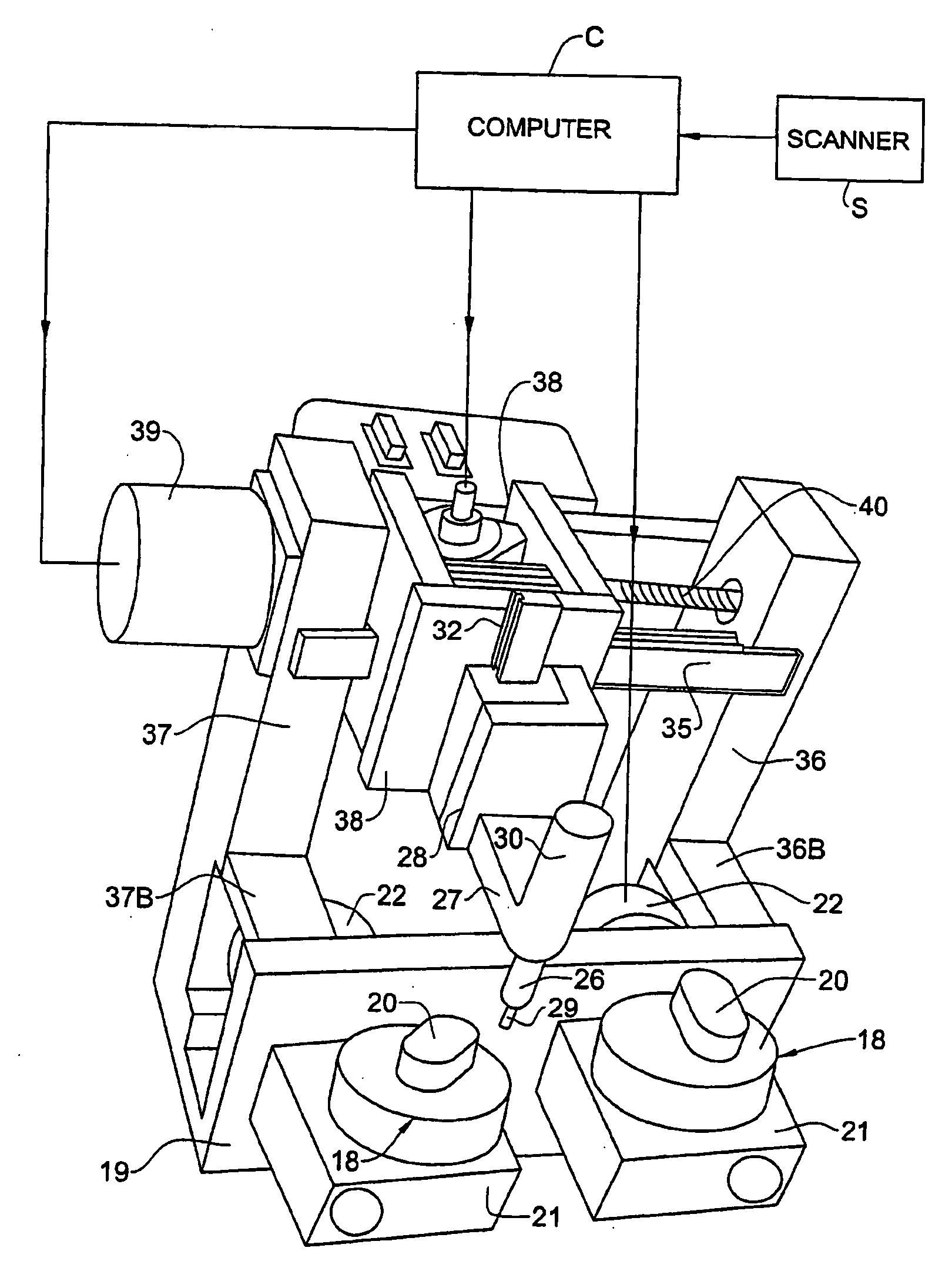
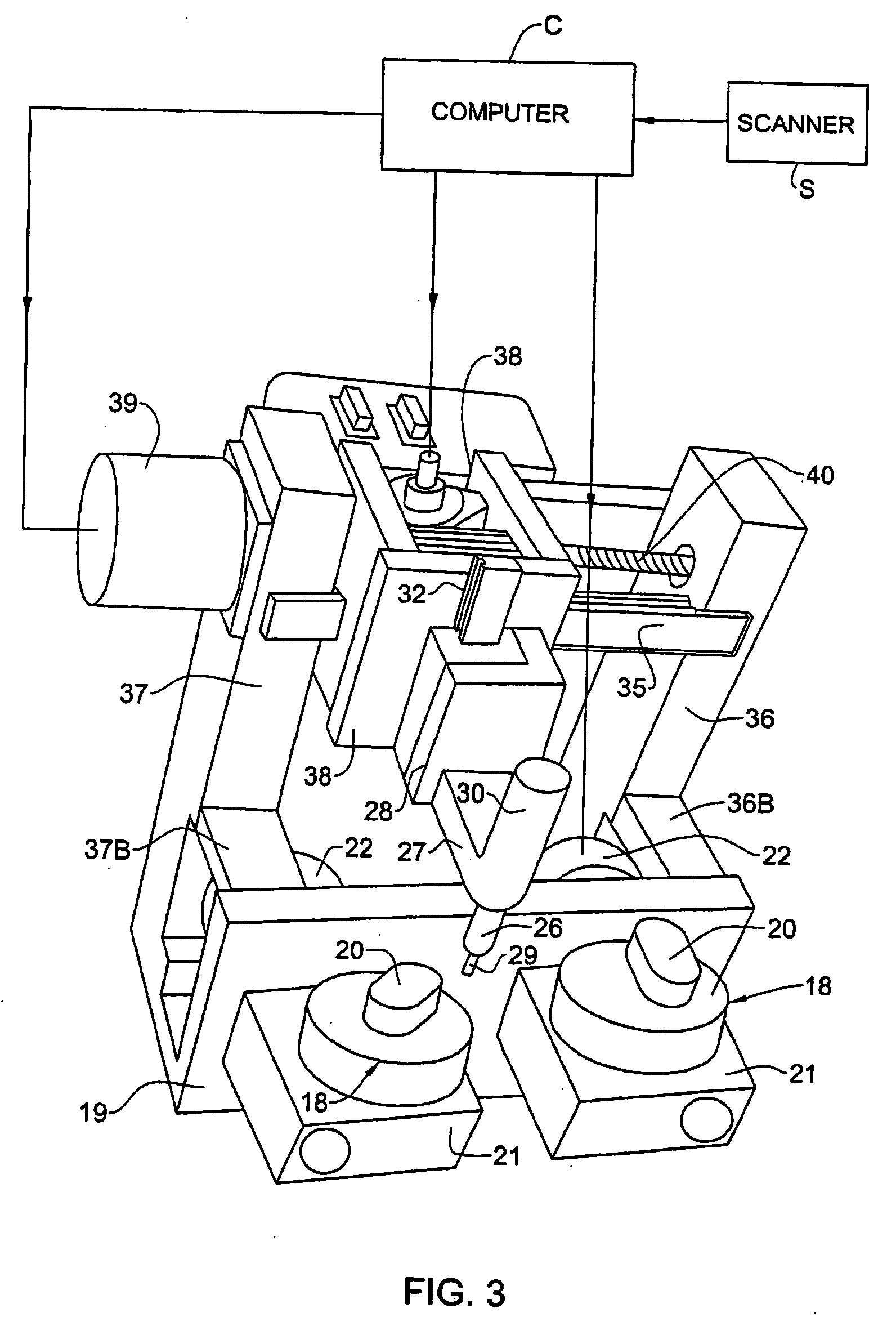
Computer-controlled milling machine for producing lenses for clip-on accessory
a technology of clip-on accessories and milling machines, which is applied in the direction of optical surface grinding machines, manufacturing tools, instruments, etc., to achieve the effect of inexpensive conversion of eyeglasses and relatively low cost of manufacturing clip-on accessories
- Summary
- Abstract
- Description
- Claims
- Application Information
AI Technical Summary
Benefits of technology
Problems solved by technology
Method used
Image

Examples
Embodiment Construction
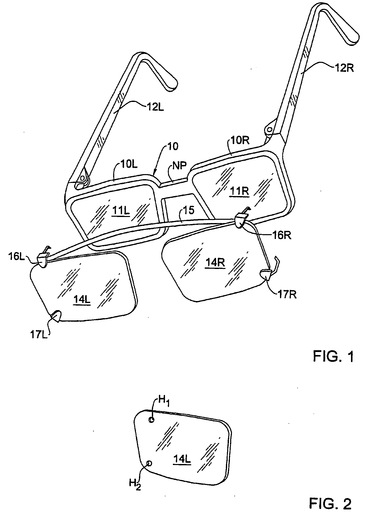
[0036] Clip-On Accessory: FIG. 1 illustrates a pair of prescription eyeglasses for correcting visual defects in the eyes of the wearer, and it also shows a clip-on accessory in accordance with the invention which is to be hitched onto these eyeglasses to protect the eyes against harmful radiation.
[0037] Included in these eyeglasses is a metal or plastic frame 10 formed by left and right half sections 10L and 10R joined together by a nosepiece NP. Mounted in the half sections of the frame are optical lenses 11L and 11R. Half sections 10L and 10R of frame 10 have a generally trapezoidal geometry, with rounded corners. The optical lenses mounted in the half sections are similarly shaped. Hinged to the half sections of the frame are temple pieces 12L and 12R.
[0038] It is to be understood that the stylized frame 10 shown in FIG. 1 is by way of example only and that whatever the actual geometry of the eyeglasses to be fitted with a clip-on accessory, the geometry of the accessory must s...
PUM
| Property | Measurement | Unit |
|---|---|---|
| Shape | aaaaa | aaaaa |
| Distance | aaaaa | aaaaa |
Abstract
Description
Claims
Application Information