
Coin selector for bimetal coins

a selector and coin technology, applied in the field of coin selectors, can solve the problems of difficulty in distinguishing authenticity and prior art cannot increase such accuracy, and achieve the effects of compact and cost-effective, accurate measurement, and verification of the authenticity of the coin

Inactive Publication Date: 2006-07-11
ASAHI SEIKO CO LTD
View PDF13 Cites 5 Cited by
  • Summary
  • Abstract
  • Description
  • Claims
  • Application Information

AI Technical Summary

Benefits of technology

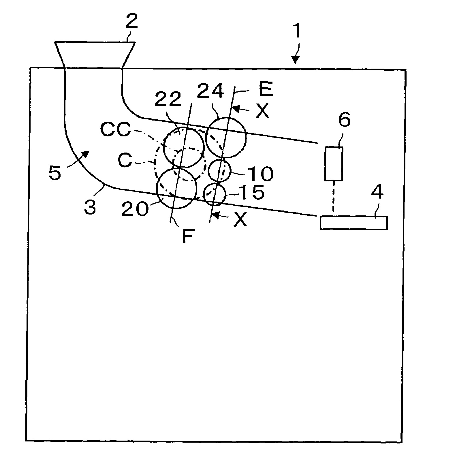
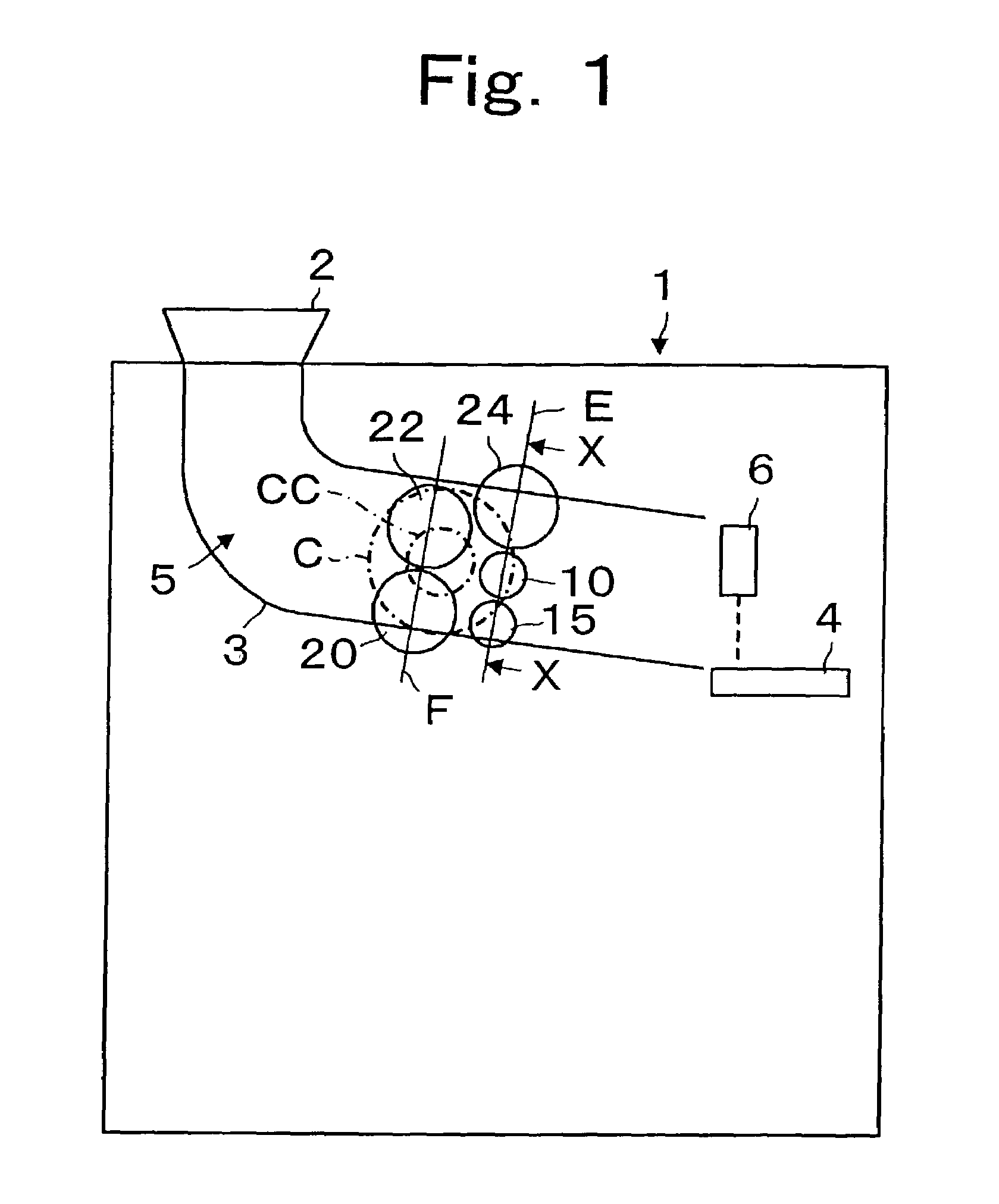
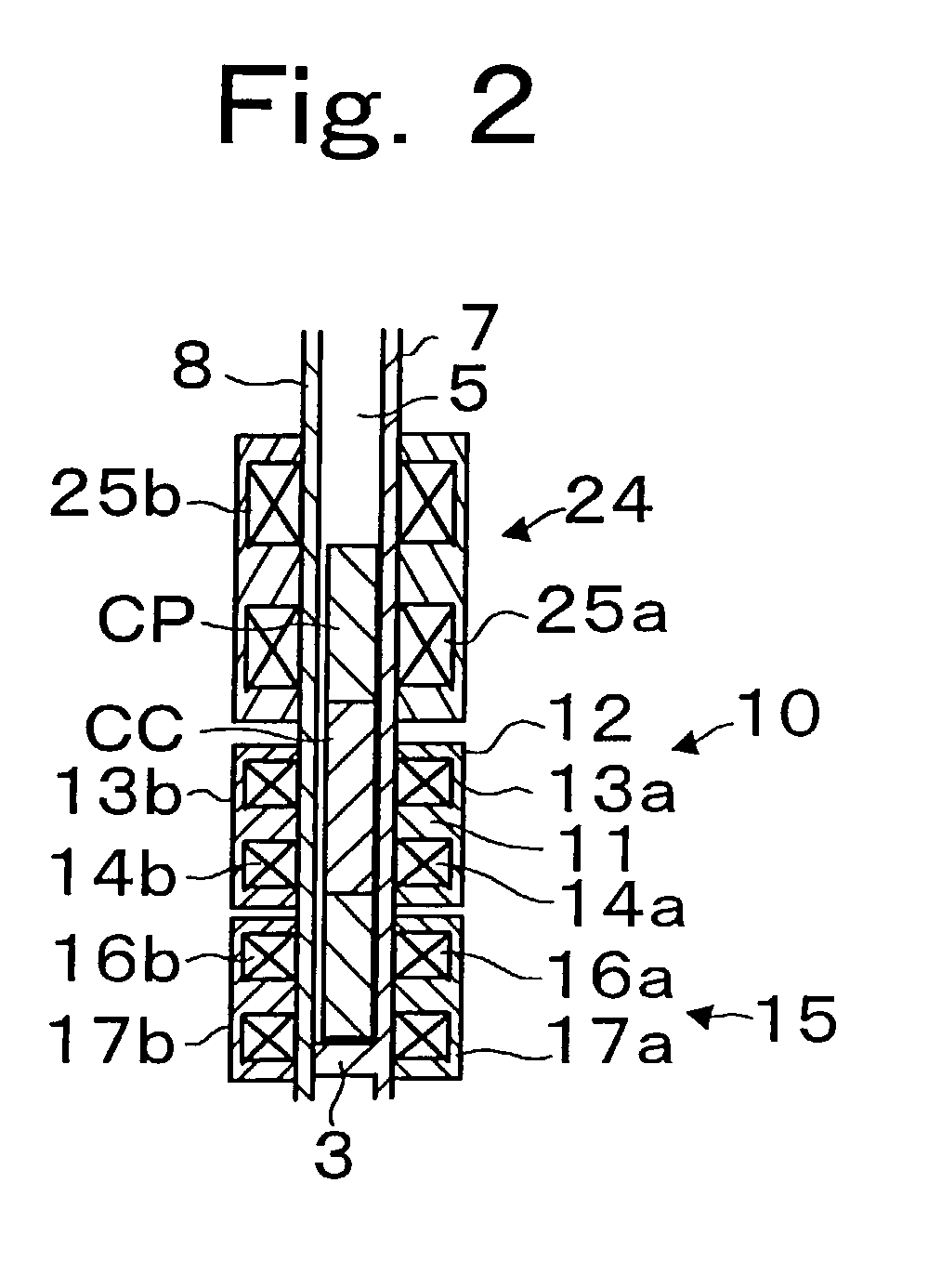
[0011]The coin selector of the present invention utilizes sensor units located along a coin passageway in which coins are guided by a guiding rail pass a plurality of thickness sensor units. Thus, the thickness of the coin can be measured at a plurality of positions. The coin's thicknesses are determined through this plurality of measurements. The thickness sensor units include a first thickness sensor unit located relative to the center of the coin as it moves and a second thickness sensor unit located relative to the rim of the coin. The output measurements from these sensor units can be compared to the values of a genuine coin which is used as a pre-stored standard value. In addition, the first thickness sensor unit and the second thickness sensor unit are located along a line which will cross a guiding rail. It can be arranged that the first thickness sensor unit and the second thickness sensor unit can measure the thickness of the same diameter positions at the same time. The first thickness sensor unit can face the center of the coin and the second thickness sensor unit can face the rim. Even if the diameter of the coin differs, accurate measurements can be made. In addition, material sensor units and diameter sensor units can be located close to the first thickness sensor unit and the second thickness sensor unit. By making comparisons of known values for the coin material that should be expected and the diameter parameters, further verification of the authenticity of the coin can be achieved. The individual sensor units can be made up of coils and by appropriate arrangement of the material sensor unit, frequency, interference with the output of the other sensor unit coils can be prevented and the coin selector can be formed in a very compact and cost-effective manner while increasing the accuracy of detection.

Problems solved by technology

However, the prior art cannot increase such accuracy when a thickness sensor unit is located to refer to the center of the coin.
When a coin uses the same center material and rim material, it is difficult to distinguish authenticity.

Method used


Image

  • Coin selector for bimetal coins
  • Coin selector for bimetal coins
  • Coin selector for bimetal coins

Examples


Embodiment Construction

[0017]Reference will now be made in detail to the preferred embodiments of the invention, examples of which are illustrated in the accompanying drawings. While the invention will be described in conjunction with the preferred embodiments, it will be understood that they are not intended to limit the invention to these embodiments. On the contrary, the intention is intended to cover alternatives, modifications and equivalents, which may be included within the spirit and scope of the invention as defined by the appended claims. Furthermore, in the following detailed description of the present invention, numerous specific details are set forth in order to provide a thorough understanding of the present invention. However, it will be obvious to one of ordinary skill in the art that the present invention may be practiced without these specific details. In other instances, well known methods, procedures, components, and circuits have not been described in detail as not to unnecessarily ob...


PUM


Abstract

A coin selector assembly includes a coin passageway having at least a pair of thickness sensor unit operatively positioned along the coin passageway to provide respective measurements of the thickness of the coin. A comparing unit compares the respective thickness signals with corresponding stored standard values representative of a genuine coin to determine the authenticity of the coin. Additional sensor unit can be positioned along the coin passageway and excited with different frequencies. Thus, a material sensor unit and a diameter sensor unit or a pair of diameter sensor unit can also be utilized.

Description

BACKGROUND OF THE INVENTION[0001]1. Field of the Invention[0002]This invention is related to a coin selector which accurately judges whether a coin is genuine or false by increasing a distinguishing accuracy of measuring the thickness of a coin and more particularly is suitable for bimetal coins which are made up of different material either at the center or the rim of the coin.[0003]2. Description of Related Art[0004]Coin selectors which distinguish between genuine and false coins have used a material detecting coil, a thickness detecting coil and a diameter detecting coil located along a coin passageway such shown in as Japan laid-open patent application 200-187746. The thickness detecting coil and the material detecting coil are located relatively to the center of the coin and the diameter detecting coil is located relatively to the rim of the coin.[0005]Therefore, the thickness of a false coin with comparable material and diameter may pass through, because machining a false coin...

Claims


Application Information

Patent Timeline
Patent Type & Authority Patents(United States)
IPC IPC(8): G07D7/00A44C21/00G06C29/00G07D5/02G07D5/08
CPCG07D5/08G07D5/02
Inventor MATUBARA, YUKINARIOHTOMO, HIROSHI
Owner ASAHI SEIKO CO LTD
Learn More