
Cable lock and method

a technology of cable locks and locks, applied in the field of cable locks and locking methods, can solve the problems of inability to identify the ingress of locks, the gap between the cable and the edge of the inlet aperture, and the inability to bypass such locks, so as to inhibit the ingress of objects

Inactive Publication Date: 2006-07-11
ALPHA CARGO TECH
View PDF20 Cites 20 Cited by
  • Summary
  • Abstract
  • Description
  • Claims
  • Application Information

AI Technical Summary

Benefits of technology

"The present invention provides a cable lock with a cable and a housing, which has a wall with an aperture and a complementary shape to the cable. The cable can move within the housing in one direction but is blocked from movement in the other direction. The cable lock can be assembled by inserting the cable into the housing and securing it with a visible indicator that is deformable under force. The cable lock can also be locked in a locked state where it is movable in one direction but restrained from movement in the other direction, and can be rotated when in the locked state. The technical effects of the invention include improved security and ease of assembly and use."

Problems solved by technology

When a cable (such as a wire cable) is inserted into the inlet apertures, gaps are present between the cable and the edge of the inlet aperture due to the gaps created between the spirals of the cable.
However, crimping the housing to around the end cap can create gaps between the edge of the end cap and the housing through which picks and other tools can be inserted to unlock the lock.
However, thieves have bypassed such cable locks by cutting the cable, using a machine or tool (e.g., a drill) to remove the cut cable from the aperture, inserting a new cable, and re-crimping the new cable in the aperture.
By using the methods discussed above and others on conventional cable locks, it is often difficult to identify that the locks have been bypassed.
In some applications (such as for trailers, cargo containers, and other mobile cargo storage units used to move cargo), the popular use of conventional cable locks is exacerbated due to the added difficulty in identifying where the theft took place during transit.

Method used


Image

  • Cable lock and method
  • Cable lock and method
  • Cable lock and method

Examples


Embodiment Construction

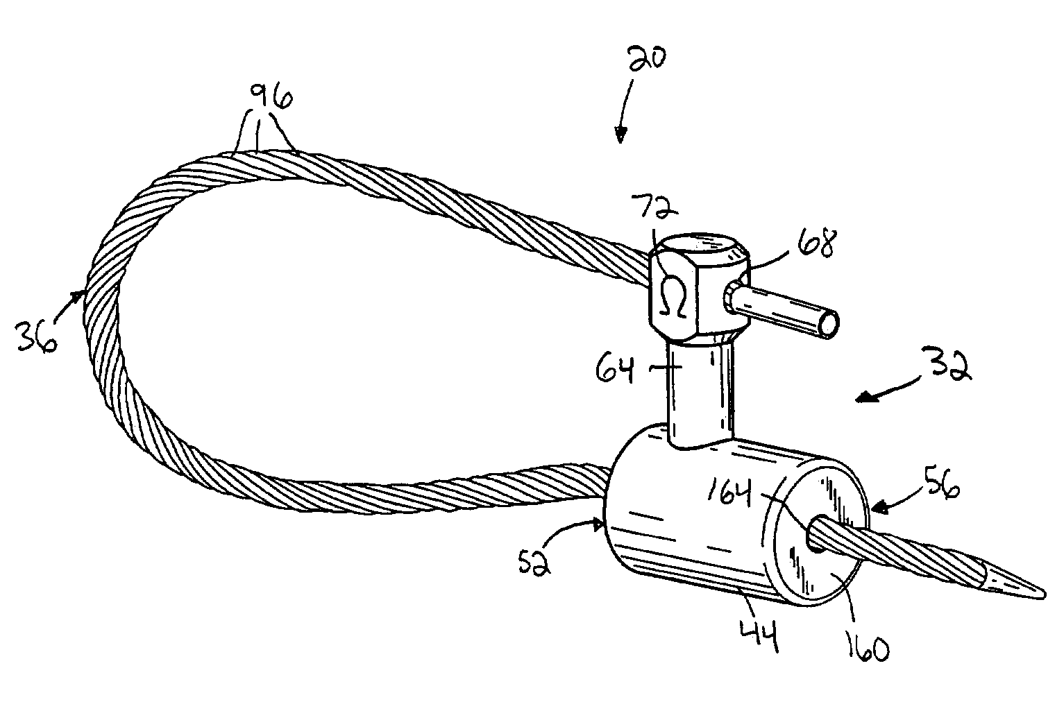
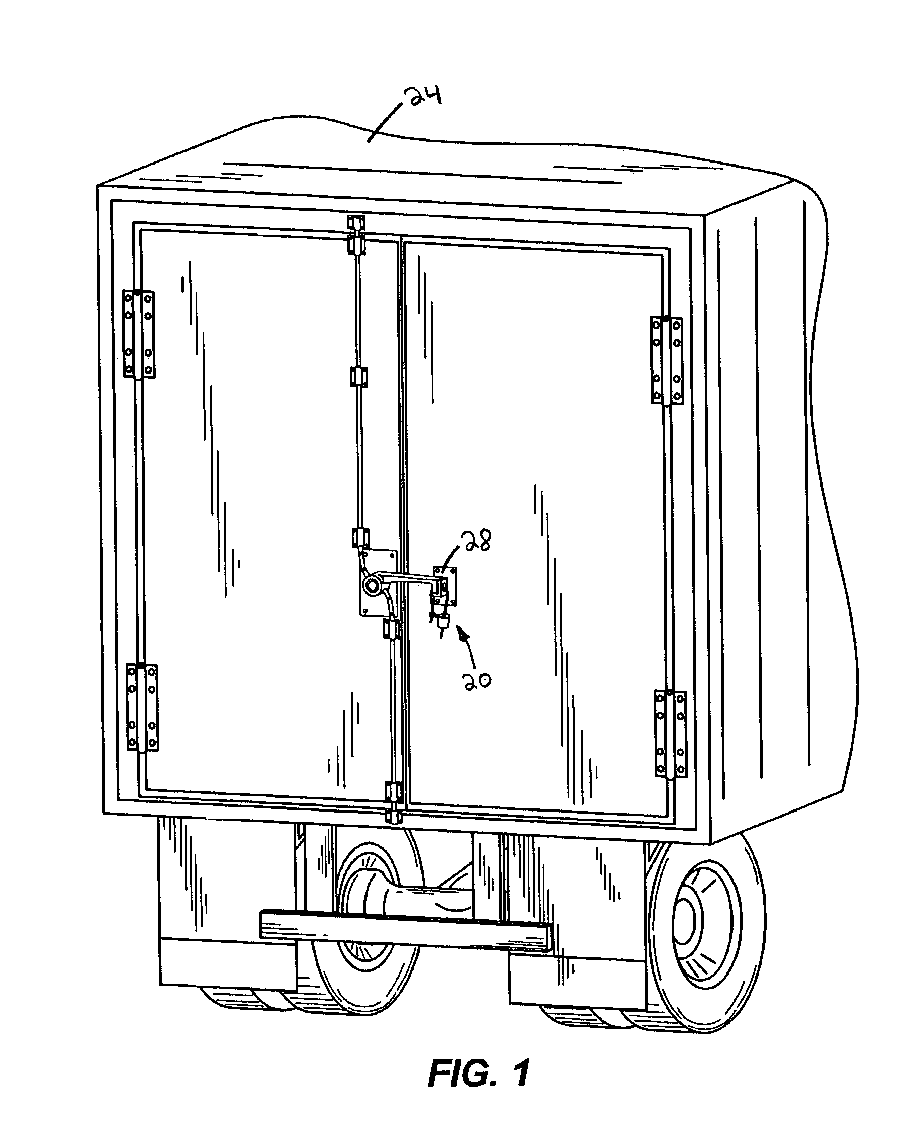
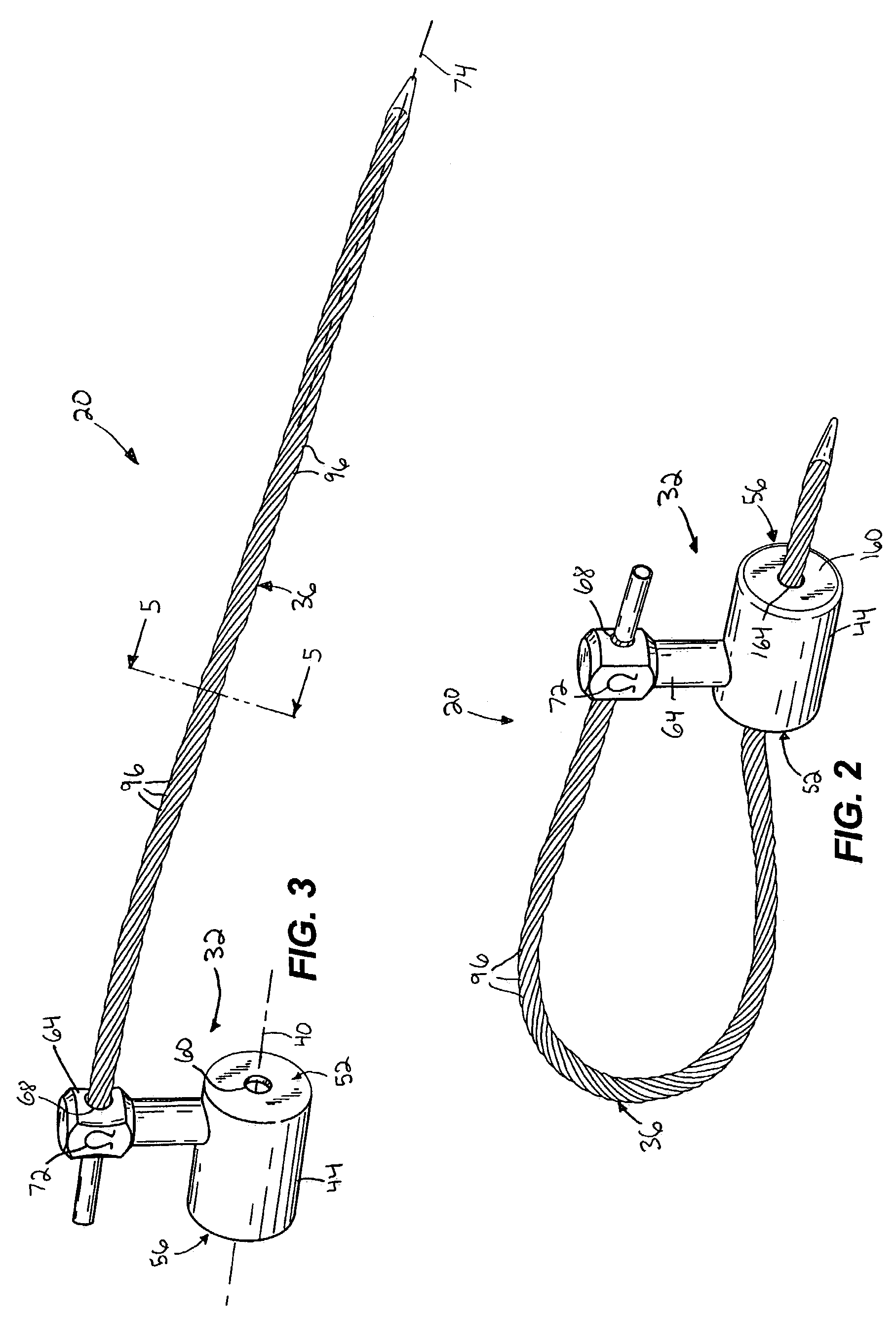
[0033]Referring to FIG. 1, a cable lock 20 according to an exemplary embodiment of the present invention is illustrated in combination with a vehicle trailer 24. Like other cable locks, the cable lock 20 can be employed to secure a wide variety of items and areas, such as, for example, trailers and cargo containers transportable by a truck, boat, train, etc., other types of containers, doors, gates, machinery, equipment, or any other item or device that can be locked or otherwise secured with a cable lock. The cable lock 20 can be employed in conjunction with any type of latch to secure the latch from release. By way of example only, and as illustrated in FIG. 1, a cable lock 20 can be used in combination with a latching device 28 mounted on a vehicle trailer 24 to lock one or more doors of the trailer 24. Alternatively, the cable lock 20 can be used to secure items and areas in other manners, such as by wrapping around handles of doors, passing a cable of the cable lock through ape...


PUM


Abstract

Some embodiments of the cable lock provide a body defining a housing in which a cable can be received to lock the cable lock. In some embodiments, the cable is rotatable with respect to the housing when the cable lock is in a locked state, thereby increasing the difficulty of circumventing the lock. The cable lock can have a wall with an aperture shaped to compliment the cross-sectional shape of the cable passed therethrough, an end wall that can be attached to the housing by rolling or crimping an edge of the housing over the end wall, and / or one or more visual indicators providing a manner by which tampering of the cable lock can be detected.

Description

FIELD OF THE INVENTION[0001]The present invention relates generally to locking apparatuses and methods, and more particularly, to cable locks and locking methods.BACKGROUND OF THE INVENTION[0002]Many varieties of locking devices exist in today's marketplace and are used to lock a variety of different devices or items. Some of these conventional locking devices are cable locks. Such conventional cable locks typically include a housing and a cable having one end connected to the housing and a second end insertable into and locked to the housing. These conventional cable locks typically use a wire cable having a plurality of metal wires twisted around each other to form a single cable. Wire cables typically have a spiraled exterior surface created by the twisting of the wires. Conventional cable locks typically have an unlocked state in which a free end of the cable is not inserted into the housing, and a locked state in which the free end of the cable is inserted into the housing and ...

Claims


Application Information

Patent Timeline
Patent Type & Authority Patents(United States)
IPC IPC(8): B65D55/06B65D90/00G09F3/03
CPCB65D90/008G09F3/0352G09F3/037B65D2211/00Y10T24/3993Y10T24/3998Y10T24/3976Y10T24/3909Y10T292/48Y10T292/491Y10T292/502Y10T292/51
Inventor FOIGEL, VENIAMIN A.MATVIEV, IGOR B.SHAPOVALOV, SERGEI F.VVEDENSKIY, URIY A.ROGKOV, SERGEI A.ROMOV, ANATOLIY A.KLEYNERMAN, GREGORY
Owner ALPHA CARGO TECH
Learn More