Eureka AIR delivers breakthrough ideas for toughest innovation challenges, trusted by R&D personnel around the world.

Threaded inner sleeve for generator magnet

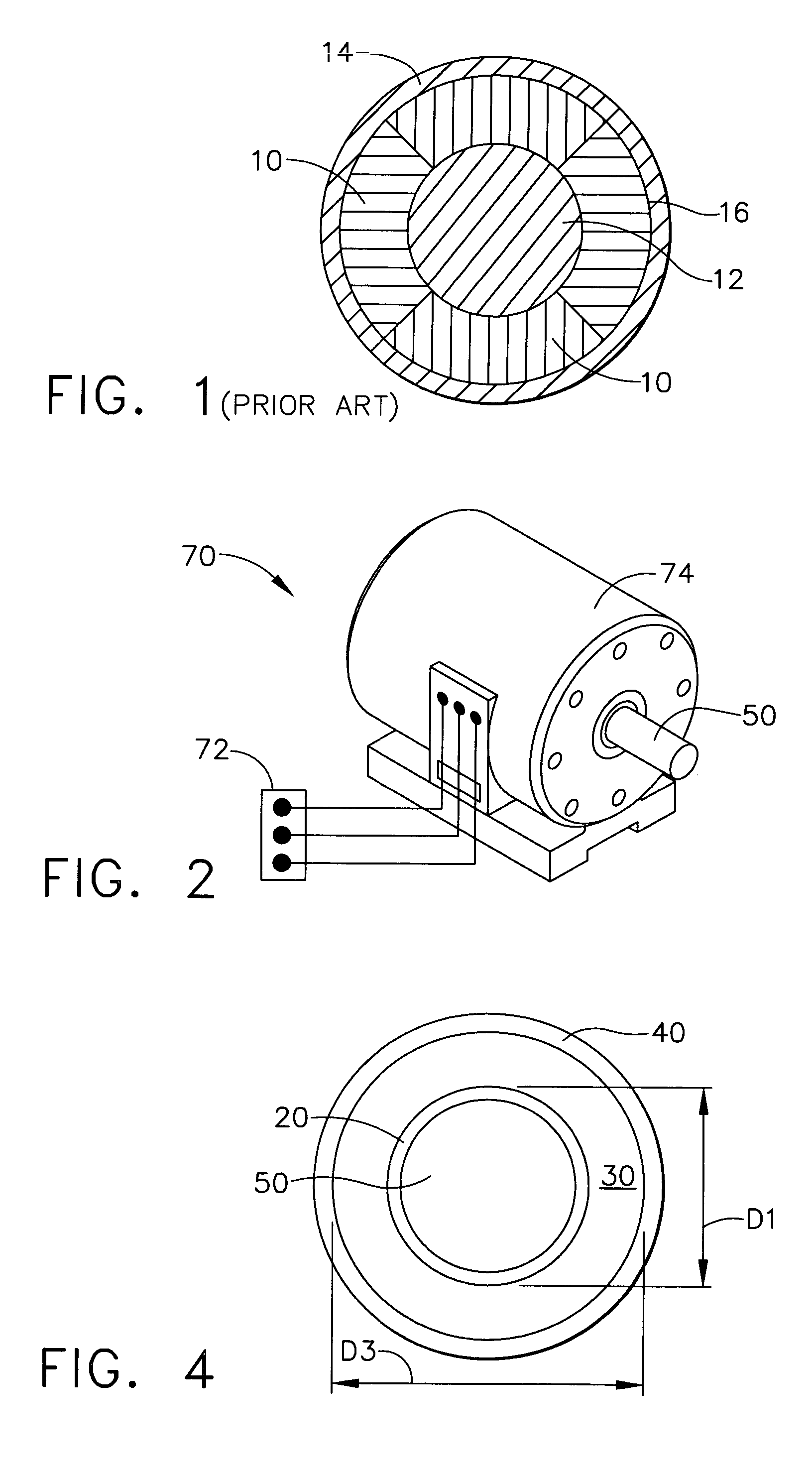
a technology of inner sleeves and magnets, which is applied in the direction of rotating magnets, magnetic circuit rotating parts, synchronous machines with stationary armatures, etc., can solve the problems of high initial manufacturing cost, frictional drag and/or damage to machine parts, and reduced machine efficiency

Active Publication Date: 2006-07-11
HONEYWELL INT INC
View PDF18 Cites 29 Cited by
  • Summary
  • Abstract
  • Description
  • Claims
  • Application Information

AI Technical Summary

Problems solved by technology

If axial movement is permitted, one or more magnets may not properly align with an armature with the consequence that machine efficiency diminishes.
If radial movement occurs, the probability of interfering contact between the rotor and the stator, and the resulting frictional drag and / or damage to machine parts come into existence.
These conventional motor and generator configuration assembly methods are complex and result in high initial manufacturing costs as well as high operational costs.
Operational costs are high due to possible rotor slippage and / or magnet cracking under operating conditions.

Method used


Image

  • Threaded inner sleeve for generator magnet
  • Threaded inner sleeve for generator magnet
  • Threaded inner sleeve for generator magnet

Examples


Embodiment Construction

[0021]The following detailed description is of the best currently contemplated modes of carrying out the invention. The description is not to be taken in a limiting sense, but is made merely for the purpose of illustrating the general principles of the invention.

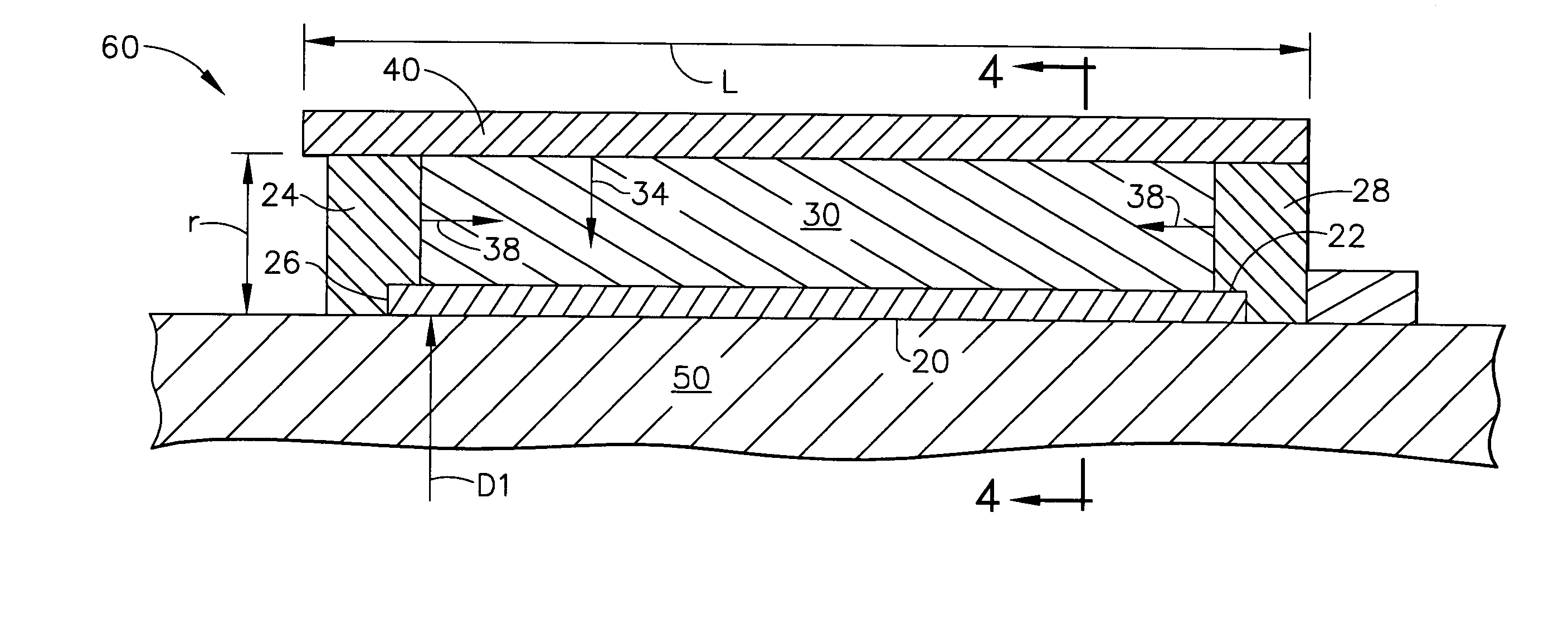
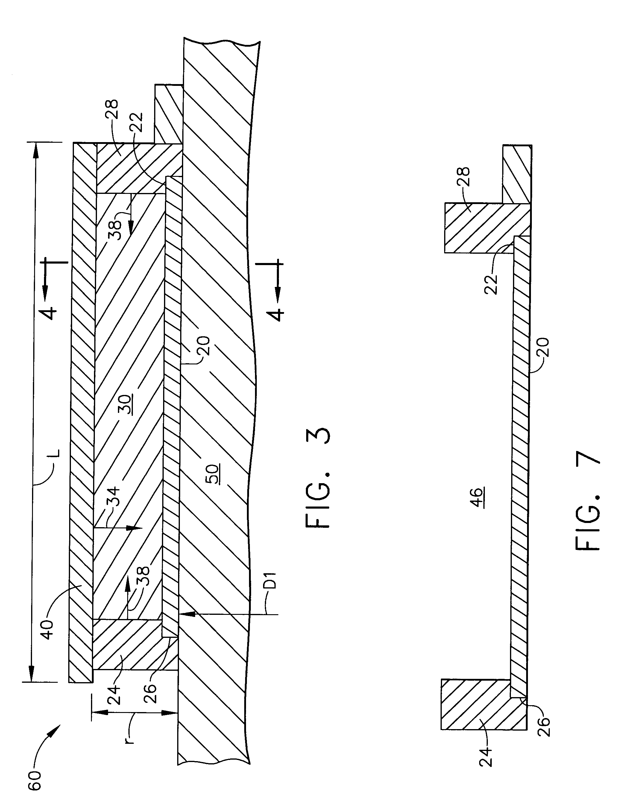
[0022]Broadly, the present invention provides for an axial constraint on the magnet of a motor or generator to provide additional insurance for the rotor to be fixed inside the magnet. As discussed above, a conventional design may require close tolerance between the outer sleeve and the magnet because thermal shrinking of the outer sleeve frictionally holds the magnet to the rotor. The present invention enlarges the required radial shrink-fit tolerance, thereby reducing time and cost of accurately matching the magnet size with the size of the outer sleeve.

[0023]Moreover, the present invention provides a compressive state on the magnet at all times, thereby preventing magnet cracking and the resulting unstable rotor. In contr...


PUM

PropertyMeasurementUnit
temperatureaaaaaaaaaa
electric currentaaaaaaaaaa

Abstract

An inner sleeve, having threads on each end, is formed on a motor or generator rotor. A pair of stub shafts are threadably attached to the inner sleeve at each end and a magnet is placed in between. The stub shafts are turned on the inner sleeve to bring them together, thereby creating an axial compressive force on the magnet. By keeping the magnet in a compressive state at all times, cracking of the magnet is prevented, thus keeping the rotor stable during use of the motor or generator. An outer sleeve is shrunk-fit around the magnet and stub shafts to provide a further radial force on the rotor. The magnet assembly of the present invention also enlarges the required radial shrink-fit tolerance of the outer sleeve on the magnet, thereby reducing costs conventionally required to match the outer sleeve to the magnet within close tolerances.

Description

BACKGROUND OF THE INVENTION[0001]The present invention generally relates a threaded inner sleeve for a magnetized rotor for the motor or generator and, more specifically, to a threaded inner sleeve that may apply an axial compressive force onto the magnet.[0002]Permanent magnet rotors are frequently used in dynamo electric machines such as motors and generators. Permanent magnets are secured to a rotor hub or shaft by any of a variety of means and care must be taken to assure that such securement prevents the magnets from moving either axially or radially. If axial movement is permitted, one or more magnets may not properly align with an armature with the consequence that machine efficiency diminishes. If radial movement occurs, the probability of interfering contact between the rotor and the stator, and the resulting frictional drag and / or damage to machine parts come into existence.[0003]Conventional motor or generator designs may use any shape magnet, so long as a hole is formed ...

Claims


Application Information

Patent Timeline
Patent Type & Authority Patents(United States)
IPC IPC(8): H02K21/12H02K1/27H02K1/28H02K5/128
CPCH02K5/128H02K1/2733H02K1/30H02K1/2753Y10T29/49012Y10T29/53161Y10T29/49009
Inventor SHIAO, SAMCHEN, ROBERT P.
Owner HONEYWELL INT INC
Why Eureka
Eureka Blog
Learn More