Assembly technology of precise cycloidal speed reducer

An assembly process and reducer technology, which is applied in transmission devices, gear transmission devices, belts/chains/gears, etc., can solve the problems of the performance impact of the whole machine, the meshing status of the rollers, and the complexity of the structure, so as to improve the assembly quality, The effect of reducing the difficulty of assembly and improving the precision of tolerance fit

Inactive Publication Date: 2017-05-31
CHONGQING UNIV +1
View PDF2 Cites 11 Cited by
  • Summary
  • Abstract
  • Description
  • Claims
  • Application Information

AI Technical Summary

Problems solved by technology

The high degree of mutual cooperation between the parts and the complex structure increase the difficulty of assembly; the reducer has multiple teeth in contact during the meshing process, and it is easy to interfere with the pin teeth and the rounded tooth profile during assembly, and improper knocking during interference Assembling will result in roller roughening and poor meshing; as a precision transmissi

Method used


Image

  • Assembly technology of precise cycloidal speed reducer
  • Assembly technology of precise cycloidal speed reducer
  • Assembly technology of precise cycloidal speed reducer

Examples


Embodiment 1

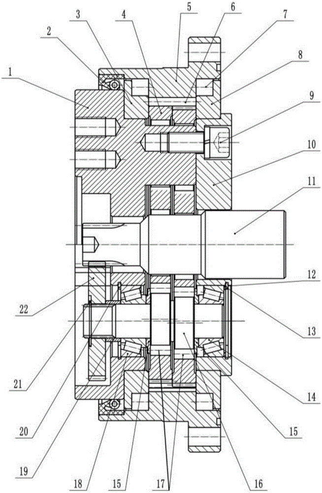
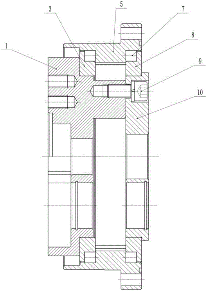
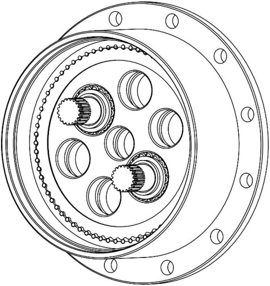
[0031] Embodiment 1. The crankshaft roller bearing of this embodiment is a full complement cylindrical roller bearing, and the support bearing is a raceway cross roller bearing, and the raceway of the cross roller bearing is integrated in the support mechanism and the internal gear. Its assembly process includes the following steps:

[0032] A. Grouping: Check the eccentric part of the crank shaft 16, the 4 coordinate holes of the circular gear, and the diameter of the pin teeth 6, group and number them; put the pin teeth 6 into the freezer to reduce the temperature of the pin teeth to -5~-20 ℃;

[0033] B. Crankshaft and Yuanli gear assembly: select the crankshaft 16 and Yuanli gear 4 with corresponding tolerances, and select the crankshaft roller 17 corresponding to the group number; Figure 5 As shown, put the crankshaft roller 17 into the full complement cylindrical roller assembly tool; then as Figure 4 As shown, put the crankshaft 16 and the crankshaft roller into the...

Embodiment 2

[0042] Embodiment 2. The crankshaft roller bearing of this embodiment is a cylindrical roller bearing without inner and outer rings with a cage, and the support bearing is a tapered roller bearing. The assembly process includes the following steps:

[0043] A. Grouping: Inspect the 16 eccentric parts of the crankshaft, the 4 coordinate holes of the circular gear, and the 6 diameters of the pin teeth, group and number them;

[0044] B. Put the needle teeth 6 and the crankshaft 16 into the freezer to reduce the temperature of the parts to -5~-20°C, select the circular gear 4 and the crankshaft roller 17 grouped with corresponding tolerances; place the crankshaft with the cage Put the roller 17 into the eccentric part of the crankshaft 16, quickly install the tapered roller bearing I, the tapered roller bearing II and the stopper 15 at both ends of the crankshaft; then put the crankshaft into the coordinate hole of the circular gear to ensure The crank shaft and the coordinate ho...


PUM


Abstract

The invention discloses an assembly technology of a precise cycloidal speed reducer. The assembly technology of the precise cycloidal speed reducer mainly comprises the following steps of A detecting and grouping key parts, B installing a crankshaft into a coordinate hole of a cycloidal gear, C installing an output disk supporting shaft into an output disk, D assembling an inner gear, E placing the cycloidal gear and a crankshaft assembly into the inner gear, F installing a pin gear, G installing an input end disk, H adjusting the axial clearance of tapered roller bearings of the crankshaft and I installing a planet wheel and a center shaft. According to the assembly technology of the precise cycloidal speed reducer, the key parts are assembled in a grouped manner, the assembly difficulty is lowered, and the tolerance fit precision is improved; shrink fitting is applied to the pin gear, so that the problem that interference is prone to happen in the installation process of the pin gear is solved, the assembly technology is reasonably optimized, and the assembly quality of the whole machine is improved.

Description

technical field [0001] The invention belongs to the field of mechanical assembly and relates to an assembly process of a precision circular reducer. Background technique [0002] As a precision transmission mechanism with few teeth differences, the precision circular reducer is composed of the first-stage spur gear reduction part and the second-stage circular gear reduction part. The specific structure mainly includes a sun gear, a planetary wheel, a crankshaft, a circular gear driven by the crankshaft, an internal gear with an arc containing groove, and a supporting mechanism. Among them, the circular gear is mainly formed by rolling the circle based on the motion on the circle, similar to the cycloid gear. The reducer has outstanding characteristics such as compact structure, large transmission ratio, high transmission precision, and strong bearing capacity. It can be widely used in industrial robot joint drive systems, aerospace, CNC machine tools, national defense weapo...

Claims


Application Information

Patent Timeline
IPC IPC(8): F16H1/32
CPCF16H1/32F16H2001/323
Inventor 李朝阳黄健陈兵奎孔霞周世才
Owner CHONGQING UNIV
Why Eureka
Try Eureka