Display system

a display system and display panel technology, applied in the field of display systems, can solve the problems of deteriorating luminance uniformity and visibility of the liquid crystal display panel, deteriorating object detection capability of the infrared camera, etc., to improve the assembling quality, improve the infrared camera object detection capability, and enhance the luminance uniformity of the liquid crystal display.

Inactive Publication Date: 2011-09-20
SAMSUNG DISPLAY CO LTD
View PDF1 Cites 27 Cited by
  • Summary
  • Abstract
  • Description
  • Claims
  • Application Information

AI Technical Summary

Benefits of technology

[0007]In exemplary embodiments of the present invention, a display system implements surface computing technology, enhances luminance uniformity of a liquid crystal display (LCD), improves object detection capability of an infrared camera, and improves assembling qualities.

Problems solved by technology

As a result, the object detection capability of the infrared camera deteriorates.
If the diffusion plate is removed to enhance the object detection capability of the infrared camera, the luminance uniformity and visibility of the liquid crystal display panel deteriorate.

Method used


Image

  • Display system
  • Display system
  • Display system

Examples


Embodiment Construction

[0050]The present invention will now be described more fully with reference to the accompanying drawings, in which exemplary embodiments of the invention are shown. The invention may, however, be embodied in many different forms and should not be construed as being limited to the embodiments set forth herein. It will be understood that when an element or layer is referred to as being “on” another element or layer, the element or layer can be directly on another element or layer or intervening elements or layers.

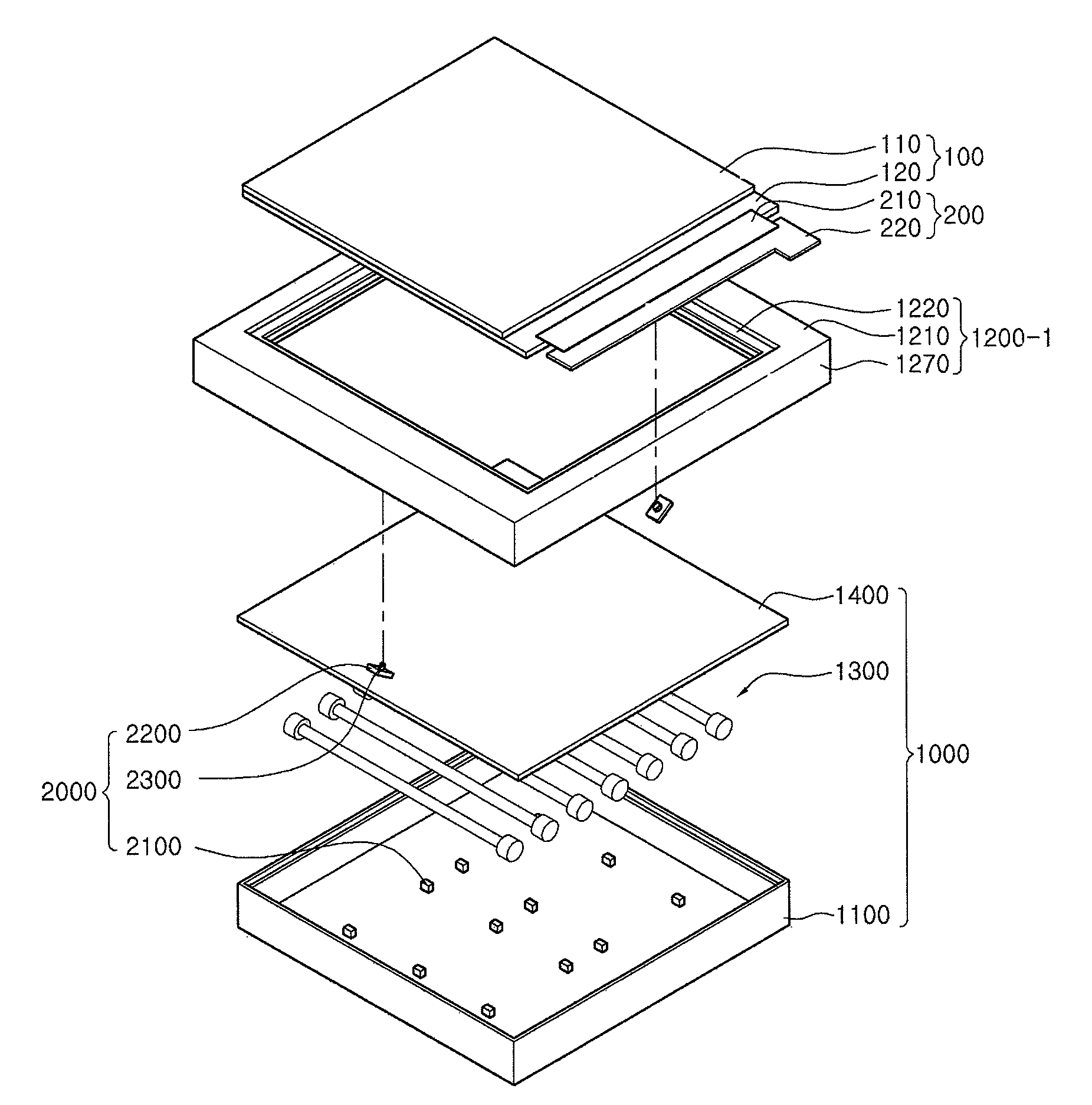
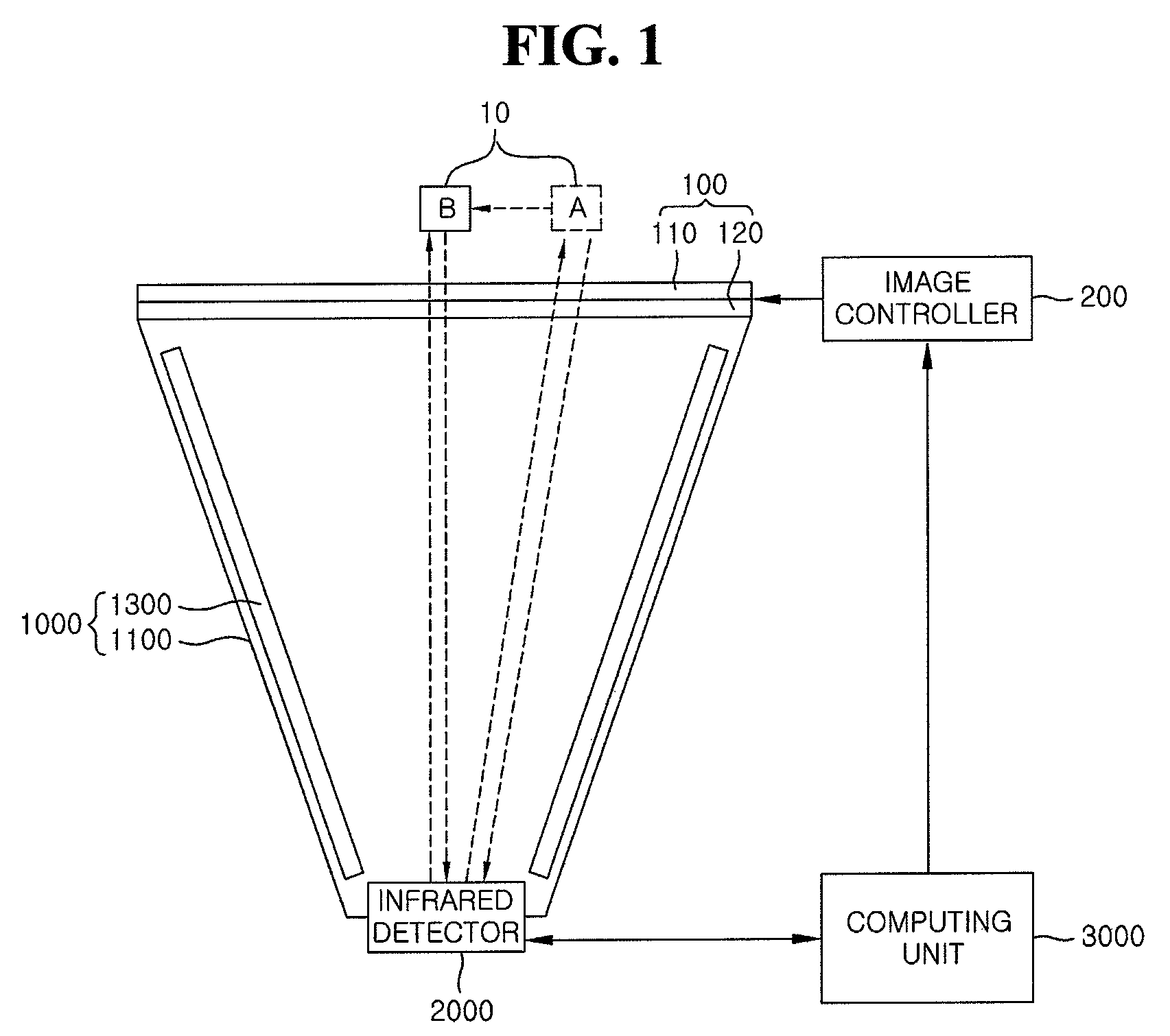
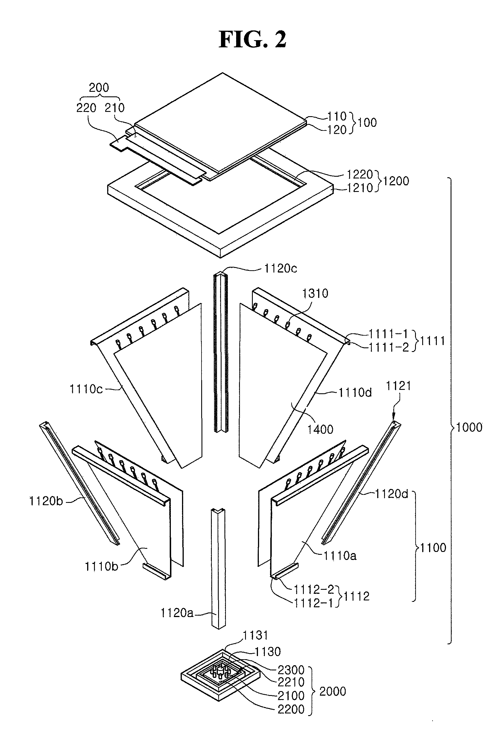
[0051]FIG. 1 is a block diagram of a display system according to an exemplary embodiment of the present invention. FIG. 2 is an exploded perspective view of a display system according to an exemplary embodiment of the present invention. FIG. 3 is a vertical cross-sectional view of a display system according to an exemplary embodiment of the present invention. FIG. 4 is a horizontal cross-sectional view of a display system according to an exemplary embodiment of the present in...


PUM

PropertyMeasurementUnit
angleaaaaaaaaaa
angleaaaaaaaaaa
angle θeaaaaaaaaaa

Abstract

A display system includes a housing member which has space therein, a plurality of light source units which are placed in the space, a diffusion member which is disposed on the light source units, a liquid crystal display panel which is disposed on the diffusion member, an infrared camera unit which is interposed between the liquid crystal display panel and the diffusion member and photograph a front region of the liquid crystal display panel, and a plurality of infrared light sources which emit infrared light to the front region of the liquid crystal display panel.

Description

CROSS-REFERENCE TO RELATED APPLICATION[0001]This application claims priority from Korean Patent Application No. 10-2008-0008506 filed on Jan. 28, 2008, the disclosure of which is incorporated herein by reference in its entirety.BACKGROUND OF THE INVENTION[0002]1. Technical Field[0003]The present disclosure relates to a display system, and more particularly, to a display system including a flat display panel using surface computing technology.[0004]2. Discussion of the Related Art[0005]Surface computing technology enables a computer to receive information about photographs, documents or objects through a screen thereof or receive information about touches on the screen. The received information is processed by the surface computing technology. A display system using the surface computing technology displays images on a screen thereof by using a projector and senses the motion of a user or an object by using an infrared camera. Thus, the display system displays an image corresponding ...

Claims


Application Information

Patent Timeline
Patent Type & Authority Patents(United States)
IPC IPC(8): G02F1/1333
CPCG02F1/13338G06F3/0425G06F3/0304G02F1/133603G02F1/133604G02F1/133608G02F2001/13312G02F2203/11G02F1/133615G02F1/13312G06F1/1601
Inventor RA, DONG-GYUN
Owner SAMSUNG DISPLAY CO LTD
Why Eureka
Try Eureka