Machine and method for shrink-fitting of shrink wrap film onto packages

a technology of shrink wrap and machine, which is applied in the direction of packaging, wrappers, transportation and packaging, etc., can solve the problems of large loss of hot air blower energy, relatively long tunnels, etc., and achieves the effects of increasing throughput, increasing throughput, and saving energy

Inactive Publication Date: 2008-06-26
KRONES AG
View PDF4 Cites 11 Cited by
  • Summary
  • Abstract
  • Description
  • Claims
  • Application Information

AI Technical Summary

Benefits of technology

[0019]Advantageously, the hood type shrink device can be moved towards the article by means of a cam, in particular a slotted control guide and can cover the packaged goods and then, following the covering, can be moved parallel to the packaged goods and, following the shrink-fitting, moved away from the packaged goods again. As a result of the cam, the movement of the hood type shrink device can be carried out in the plane perpendicular to the conveying plane such that a jerk-free and collision-free movement of the hood type shrink device is enabled, simultaneously leading to even heating of the shrink film.
[0020]Preferably, heat can also be fed to the packaged goods from underneath. Usually, a film is laid round the packaged goods, in particular a packing unit, which overlaps under the packing unit. This has the advantage that the joint seam is not visible to the user. Provision of the heating means under the packaged goods means that the shrinking and the welding of the two film ends to one another can be carried out simultaneously.
[0021]Preferably, in the covering condition, the hood type shrink device can open a flap under the conveyor, in particular via cams, so that the heat can be supplied from underneath. Thus, heat is only supplied from underneath when packaged goods are situated over the flap, and this results in further energy savings.
[0022]Preferably, after the shrink-fitting, the hood type shrink device can be returned via a second transport...

Problems solved by technology

However, these known shrink-fit tunnels have the disadvantage that, due to the conveying movement of the packing unit in the tunnel and the design of the tunnel for packaged goods of different sizes, said tun...

Method used


Image

  • Machine and method for shrink-fitting of shrink wrap film onto packages
  • Machine and method for shrink-fitting of shrink wrap film onto packages
  • Machine and method for shrink-fitting of shrink wrap film onto packages

Examples


Embodiment Construction

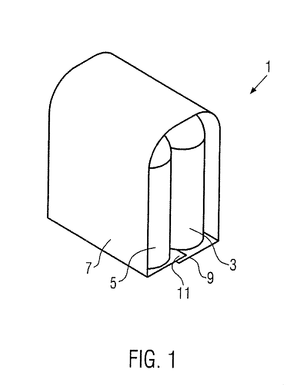
[0032]FIG. 1 shows a packing unit 1 comprising a plurality of bottles 3, 5 which is partly wrapped round with a shrink film 7. The packing unit 1 shown in FIG. 1 is an example of packaged goods that are packaged in a machine for shrink-fitting shrink film according to the disclosure, as explained in relation to the other drawings.

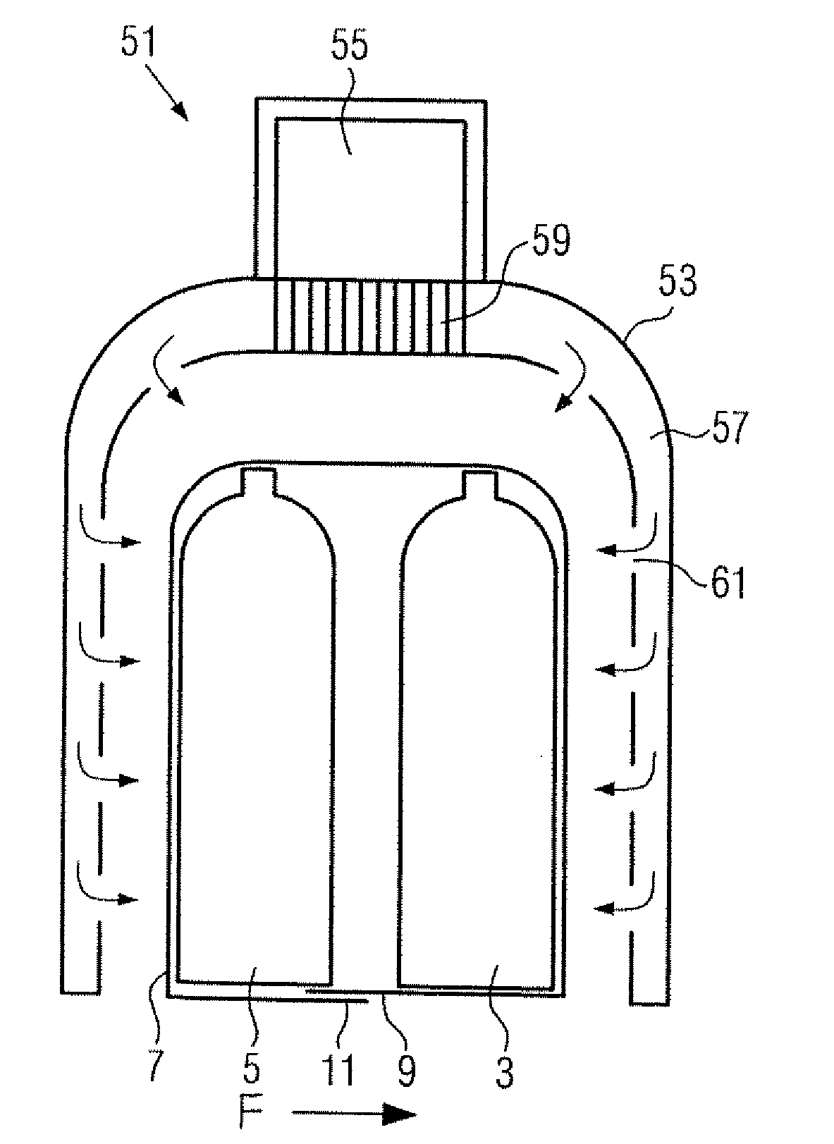
[0033]Normally, as shown in FIG. 1, a strip of shrink film of a predetermined length is laid, matched to the packing unit, round the bottles 3, 5 such that the two ends 9 and 11 cross or overlap each other over an area under the bottles 3, 5. The openings produced at the side of the packing unit 1 by the covering with the shrink film 7 are referred to here as “film openings”.

[0034]Before the shrinking, the shrink film 7 lies loosely and usually does not hold the bottles 3, 5 together. Following the shrinking, the shrink film 7 lies closely against the bottles 3, 5 and, at least partially, closes the film openings. Usually, during the shrinking process, the ...


PUM


Abstract

A machine and method for shrink-fitting shrink film onto packaged goods, in particular for packaging packing units, having a conveyor for transporting the packaged goods. In order to reduce the energy consumption and simultaneously to improve the shrinking result, the machine has hood type shrink devices which are moved along at least a part of the path with the packaged goods moved on the conveyor.

Description

CROSS-REFERENCE TO RELATED APPLICATION[0001]The present application claims the benefit of priority of German Patent Application No. 10 2006 060 109.2 filed Dec. 20, 2006. The entire text of the priority application is incorporated herein by reference in its entirety.FIELD OF THE DISCLOSURE[0002]The disclosure relates to a machine and a method for shrink-fitting shrink film onto packaged goods.BACKGROUND[0003]Machines of this type are known, for example, from EP 1 288 129. This document describes a shrink-fit tunnel in which packaged goods, such as packing units with bottles, cans or the like are conveyed on a conveyor belt through a tunnel. In the tunnel, hot air blowers ensure that the shrink film surrounding the packaged goods is heated and shrunk onto the packing unit. However, these known shrink-fit tunnels have the disadvantage that, due to the conveying movement of the packing unit in the tunnel and the design of the tunnel for packaged goods of different sizes, said tunnels a...

Claims


Application Information

Patent Timeline
IPC IPC(8): B65B53/02
CPCB65B53/066
Inventor ELSPERGER, STEFAN
Owner KRONES AG
Why Eureka
Try Eureka