Combination tool presetter and induction heat-shrink apparatus

a technology of induction heat shrinking machine and tool assembly, which is applied in the direction of manufacturing tools, electric/magnetic/electromagnetic heating, chucks, etc., can solve the problems of affecting productivity, moving the tool assembly to a secondary cooling system may be dangerous to the operator, and the accuracy of the final measurement is also affected

Inactive Publication Date: 2010-03-04
PARLEC
View PDF11 Cites 10 Cited by
  • Summary
  • Abstract
  • Description
  • Claims
  • Application Information

AI Technical Summary

Benefits of technology

[0007]The precision rotating spindle is adapted to return to a home measuring position subsequent to the cooling of the tool assembly. The precision rotating spindle may be precisely located in the home measuring position. In particular, the precision rotating spindle is precisely located axially in the home measuring position by three hardened rest buttons. The hardened rest buttons are ported axially with pressurized air to remove contaminants while the precision rotating spindle is being located. The precision rotating spindle is precisely located radially in the home measuring position by a linear moving ball cage assembly. The linear moving ball cage assembly has an interference fit to a locating diameter of the spindle which removes any contaminants from the locating surface. The travel of the precision rotating spindle is actuated via a pneumatic cylinder. The pneumatic cylinder is equipped with valving that allows the precision rotating spindle to remain in the home measuring position when the pressurized air source is removed.

Problems solved by technology

Another issue related the heat-shrinking process is returning the tool and tool holder to ambient temperature to create the tool assembly.
Such a delay as a result of the cooling process negatively affects productivity.
Additionally, moving the tool assembly to a secondary cooling system may be dangerous to the operator if he / she is required to handle a hot cutting tool assembly.
The accuracy of the final measurements is also affected due to growth / shrinkage of the tool assembly as a result of the temperature changes during the heat-shrink process.
Finally, current methods that cool the tool assembly while still in the presetter / heat-shrink machine are limited in accuracy because the heat from the hot cutting tool over time increases the temperature of the spindle that holds the tool assembly causing dimensional changes that will affect the final measurements.

Method used


Image

  • Combination tool presetter and induction heat-shrink apparatus
  • Combination tool presetter and induction heat-shrink apparatus
  • Combination tool presetter and induction heat-shrink apparatus

Examples


Embodiment Construction

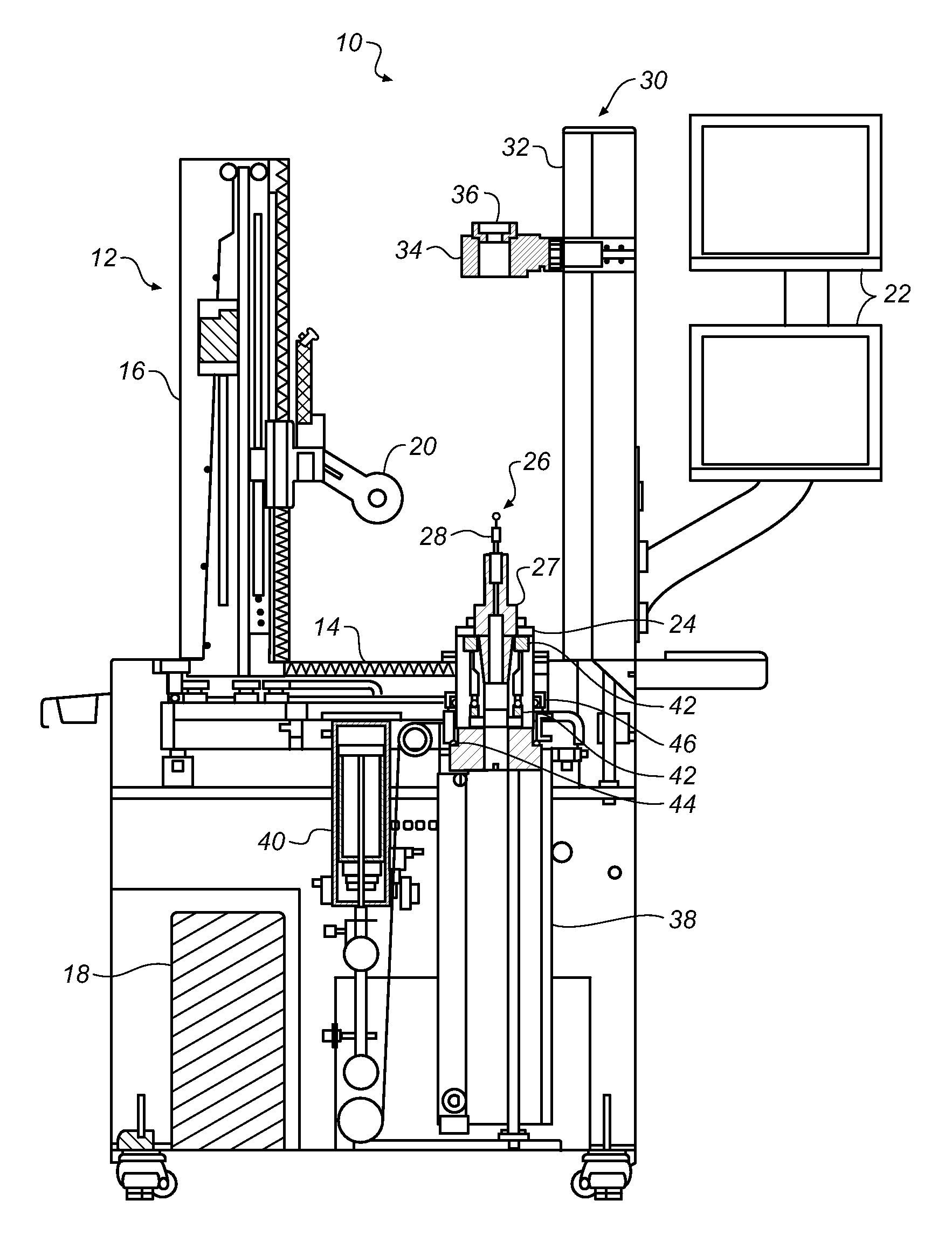
[0012]The present invention is a combination tool presetter and induction heat-shrink apparatus. In particular, the present invention provides a combination tool presetter and induction heat-shrink apparatus which utilizes a cooling system that allows for higher precision positioning of the tool within the shrink-fit tool holder.

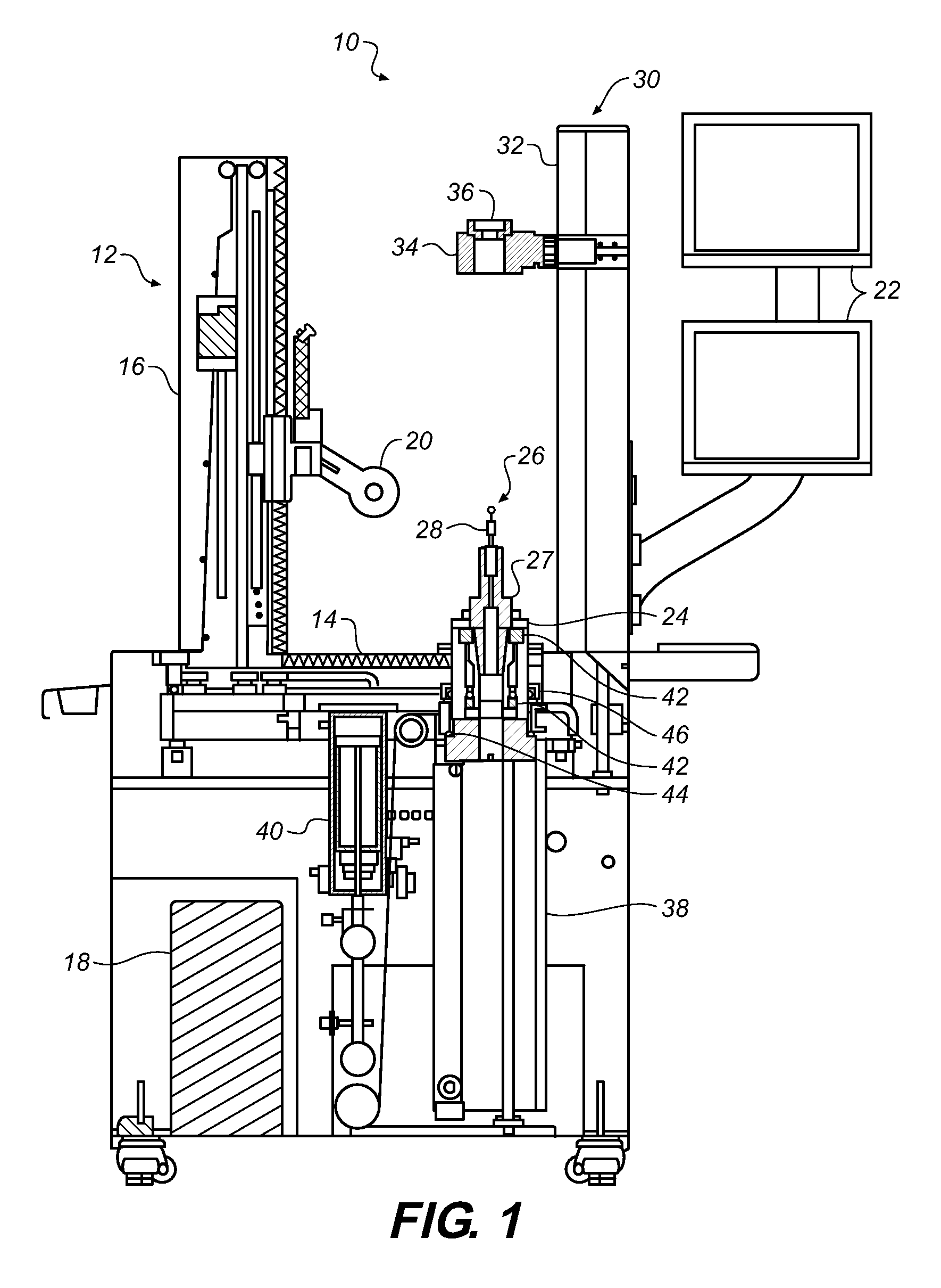
[0013]FIG. 1 depicts a combination tool presetter and induction heat shrink apparatus 10 in accordance with the present invention. The tool presetter 12 consists of a rigid base 14 and a vertical presetter column 16. The presetter column 16 is horizontally moveable along the base 14 of the tool presetter 12. The presetter column 16 may be positioned either mechanically by an operator or electronically through the use of servo motors. Further, the positioning of the presetter column 16 may be controlled through a computer system 18. The presetter column 16 supports an optical measuring device 20. The optical measuring device 20 is linearly moveable along the ...


PUM

PropertyMeasurementUnit
temperaturesaaaaaaaaaa
diameteraaaaaaaaaa
heataaaaaaaaaa

Abstract

An apparatus is disclosed for accurately positioning a tool within a shrink-fit tool holder. The apparatus includes a combined tool presetter and heat-shrink device. The tool assembly is placed in a precision rotating spindle that is able to travel into a contained location for cooling of the tool assembly subsequent to heating the tool assembly through induction. The apparatus is adapted such that the precision rotating spindle precisely returns to a home measuring position subsequent to cooling for final measurement of the tool assembly. The presetter allows for measurements related to the tool assembly both prior to and subsequent to the shrink-fitting process.

Description

FIELD OF THE INVENTION[0001]The present invention relates generally to an apparatus for the assembly of tools within tool holders and in particular to an apparatus for accurately positioning a tool within a shrink-fit tool holder. More specifically, the invention is a combination tool presetter and induction heat shrink machine which utilizes a cooling system that allows for higher precision positioning of the tool within the shrink-fit tool holder.BACKGROUND OF THE INVENTION[0002]The process of shrink-fitting tools in tool holders is a well known practice in the machining industry. One important aspect of machining processes utilizing heat-shrinking relates to accurately presetting the position of the tool within the shrink-fit tool holder. As such, combination tool presetter and induction heat shrink machines have been developed which allow a user to preset the positioning of a tool during the heat-shrink process and to make final measurements related to the positioning of the too...

Claims


Application Information

Patent Timeline
Patent Type & Authority Applications(United States)
IPC IPC(8): H05B6/14B23P11/00B23Q17/22B23B31/117
CPCB23P11/027B23Q17/0923Y10T29/53439Y10T29/49865Y10T29/4978Y10T29/49771Y10T29/53704
Inventor WITTELS, VICTORHOYT, MATTHEW
Owner PARLEC
Why Eureka
Try Eureka