Device and method for communicating data signals through multiple power line conductors

a data signal and power line technology, applied in data switching networks, wireless systems/telephones, electric controllers, etc., can solve problems such as many challenges to overcome, limited data signal strength that can be injected onto power lines, and overhead power lines that are not designed to provide high speed data communication

Inactive Publication Date: 2006-07-11
CURRENT TECH
View PDF433 Cites 340 Cited by
  • Summary
  • Abstract
  • Description
  • Claims
  • Application Information

AI Technical Summary

Problems solved by technology

While the concept may sound simple, there are many challenges to overcome in order to use power lines for data communication.
Overhead power lines are not designed to provide high speed data communications and are very susceptible to interference.
Additionally, federal regulations limit the amount of radiated energy of a power line communication system, which therefore limits the strength of the data signal that can be injected onto power lines (especially overhead power lines).
Power system transformers are one obstacle to using power distribution lines for data communication.
As such, power line communication systems face the challenge of communicating the data signals around, or through, the distribution transformers.

Method used


Image

  • Device and method for communicating data signals through multiple power line conductors
  • Device and method for communicating data signals through multiple power line conductors
  • Device and method for communicating data signals through multiple power line conductors

Examples


embodiment

Bypass Device Embodiment

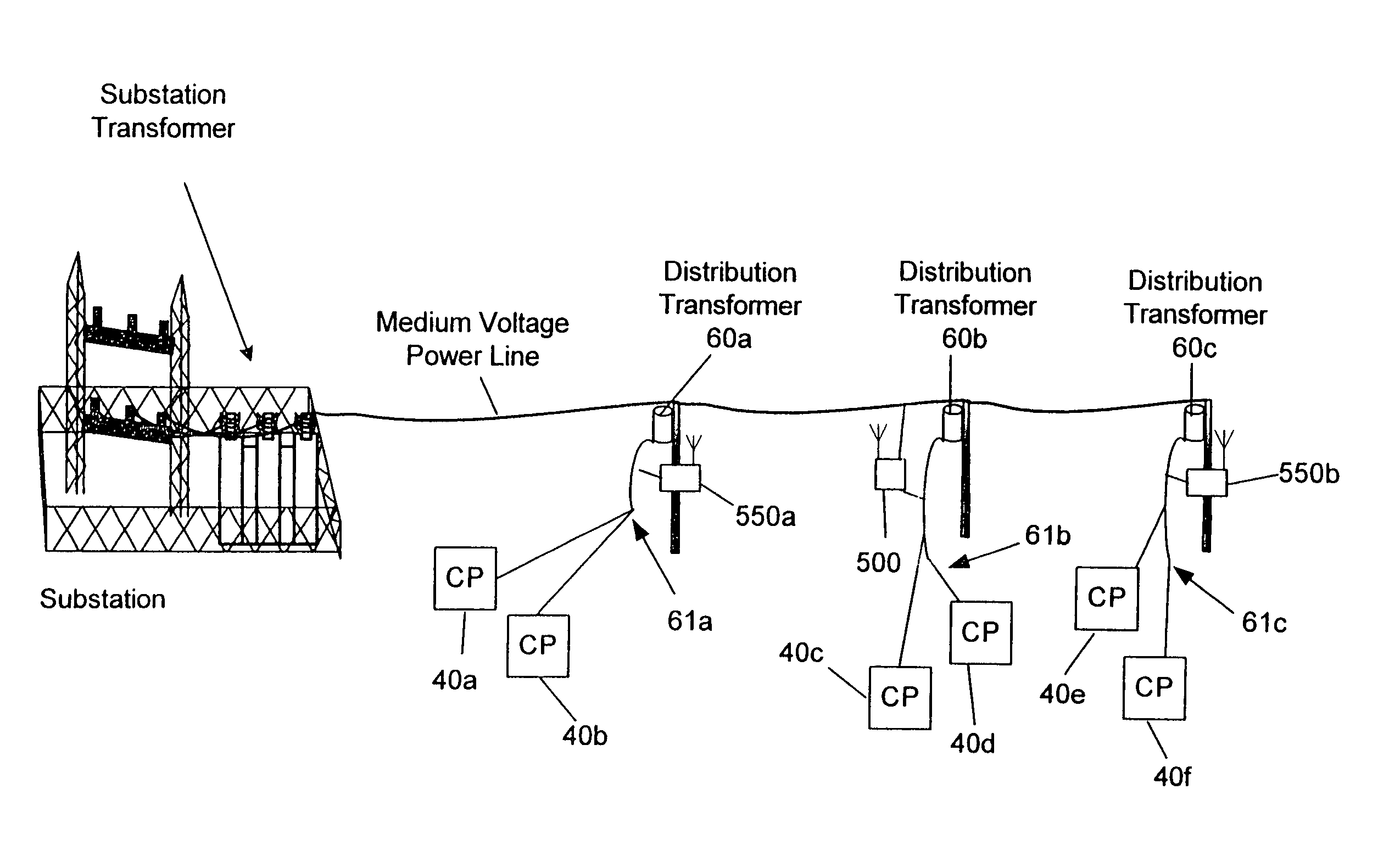
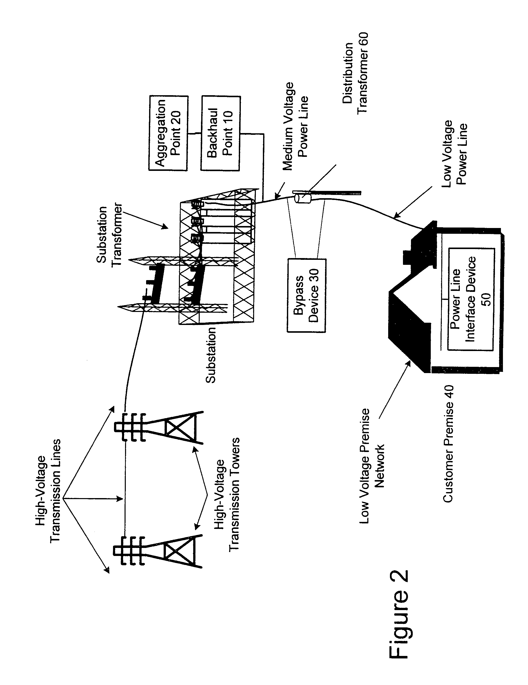
[0048]The following description is for a communication device of the present invention that is embodied as a BD. In particular, the embodiment described immediately below is a BD for bypassing a pole-mounted transformer. The present invention is equally applicable for use in bypassing other types of transformers (such as pad mount and underground) and in other applications (such as repeaters and backhaul points) with minor modifications that will be evident to those skilled the art. The BD may provide a path for data to bypass the transformer by being coupled to the same MV power line conductor that the transformer is coupled or to a different MV power line conductor and, in either instance, may be coupled to the same LV power lines to which the transformer is coupled.

[0049]The BD described herein, which is an example embodiment of the present invention, provides bi-directional communications and includes the functional block diagrams shown in FIG. 4. In part...


PUM


Abstract

The present invention provides a device for providing communications through power lines comprised of multiple conductors by transmitting the data signals through a plurality of the conductors. One embodiment of the present invention may be comprised of a transmit circuit communicatively coupled to a first energized conductor for applying a first voltage signal representing the data to the first energized conductor; the transmit circuit being communicatively coupled to a second energized conductor for applying a second voltage signal representing the data to the second energized conductor; and wherein the second voltage signal is opposite in polarity to said first voltage signal.

Description

FIELD OF THE INVENTION[0001]The present invention generally relates to data communications over a power distribution system and more particularly, to a device for facilitating communications through power lines and method of using the same.BACKGROUND OF THE INVENTION[0002]Well-established power distribution systems exist throughout most of the United States, and other countries, which provide power to customers via power lines. With some modification, the infrastructure of the existing power distribution systems can be used to provide data communication in addition to power delivery, thereby forming a power line communication system (PLCS). In other words, existing power lines, that already have been run to many homes and offices, can be used to carry data signals to and from the homes and offices. These data signals are communicated on and off the power lines at various points in the power line communication system, such as, for example, near homes, offices, Internet service provid...

Claims


Application Information

Patent Timeline
Patent Type & Authority Patents(United States)
IPC IPC(8): G05B11/01H04B3/54H04B3/56
CPCH04B3/54H04B3/56H04B2203/5487H04B2203/5466H04B2203/5441
Inventor GIANNINI, PAUL M.YANEY, DAVID STANLEYMOLLENKOPF, JAMES DOUGLAS
Owner CURRENT TECH
Why Eureka
Try Eureka