Manifold with integrated pipe for a heat exchanger

Inactive Publication Date: 2006-07-18
VALEO THERMIQUE MOTEUR
View PDF27 Cites 5 Cited by
  • Summary
  • Abstract
  • Description
  • Claims
  • Application Information

AI Technical Summary

Benefits of technology

[0017]It is thus possible to produce all the elements of the manifold, including the pipe, from metal pieces, shaped especially by stamping, which are then assembled by brazing.
[001

Problems solved by technology

The design of these pipes poses many problems in practice, given that they have to be placed at precise places on the wall depending on the conditions dictated by the placing of

Method used


Image

  • Manifold with integrated pipe for a heat exchanger
  • Manifold with integrated pipe for a heat exchanger
  • Manifold with integrated pipe for a heat exchanger

Examples


Embodiment Construction

[0048]In the various figures, like reference numerals refer to like parts, unless otherwise specified.

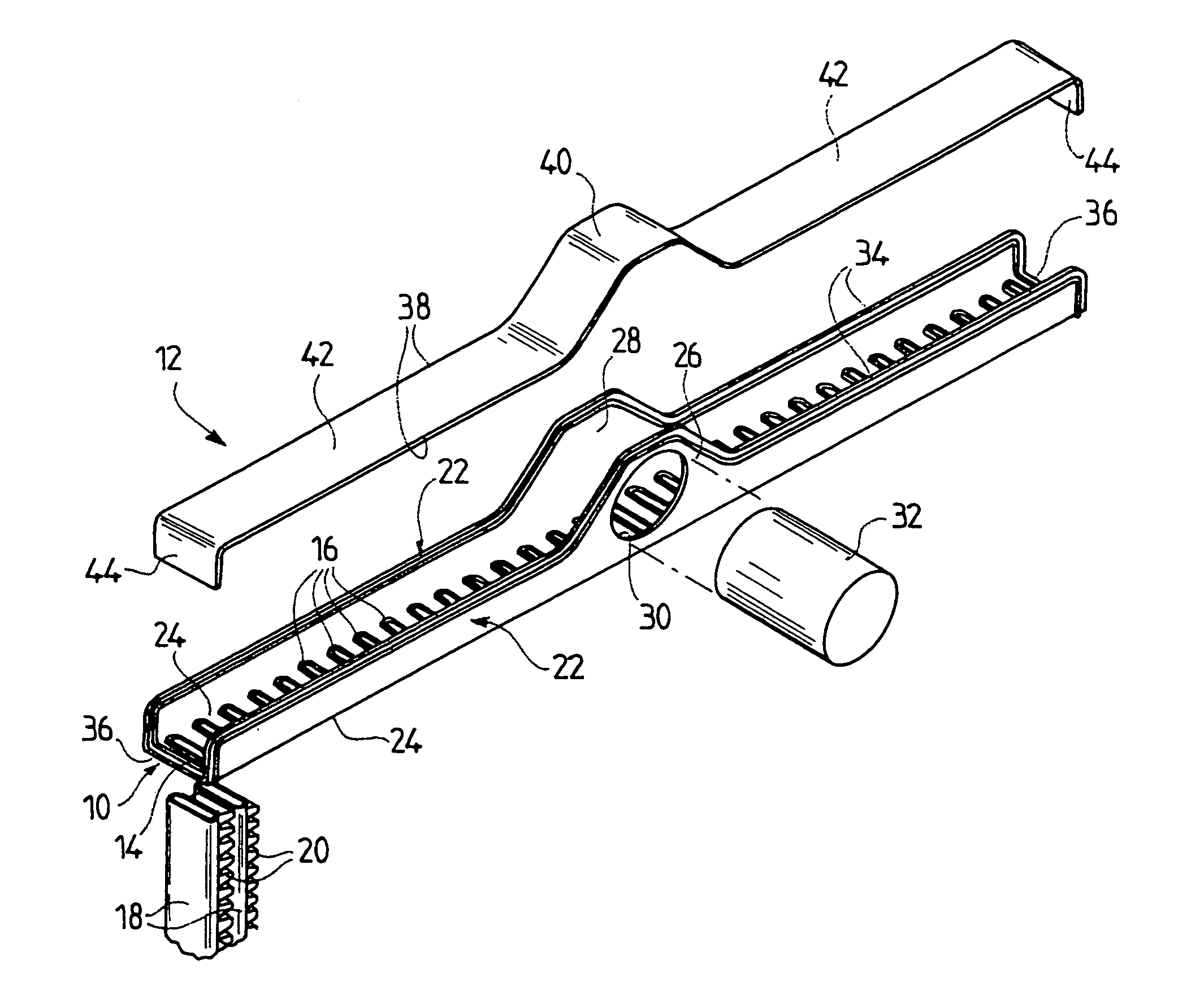
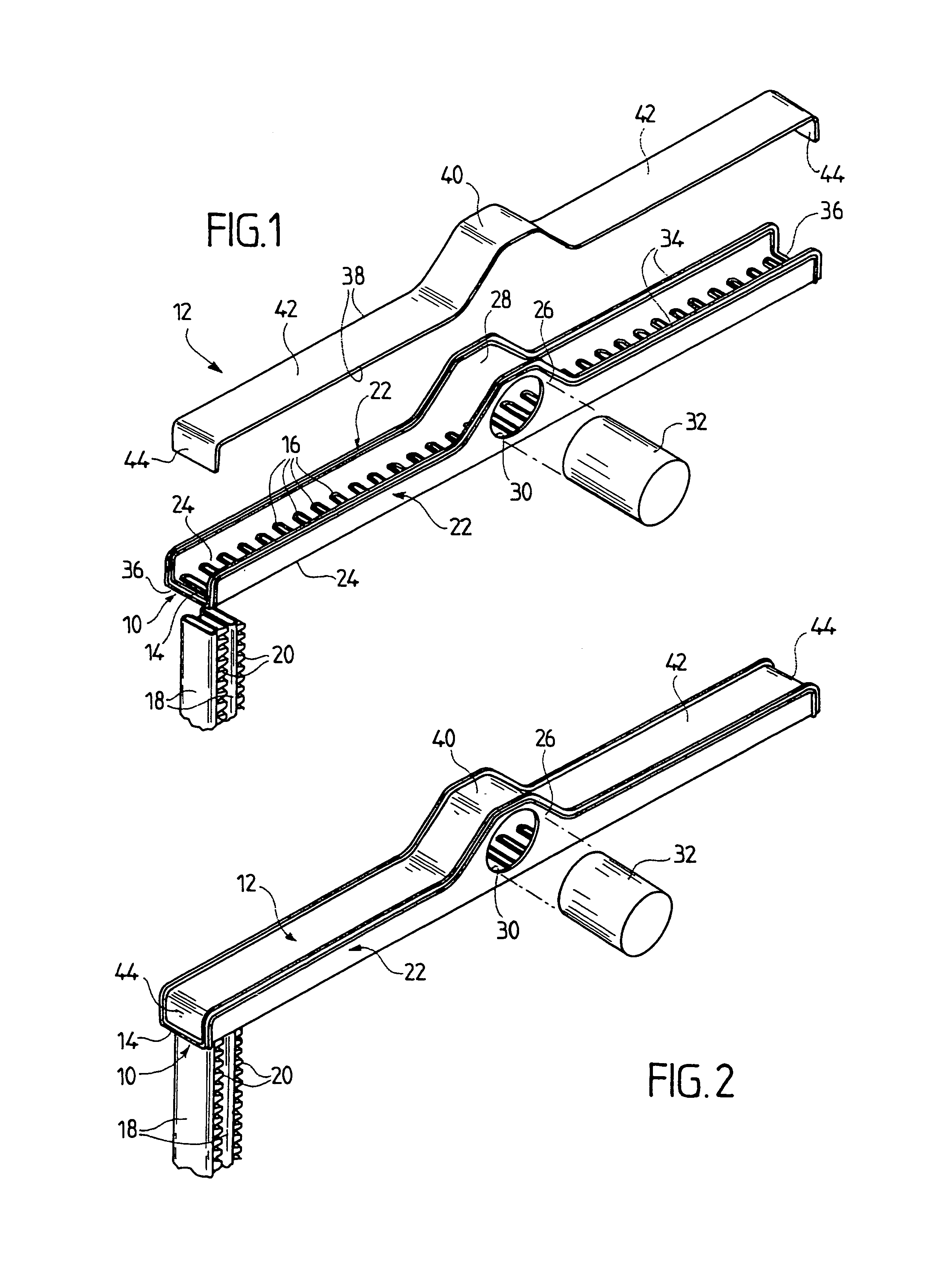
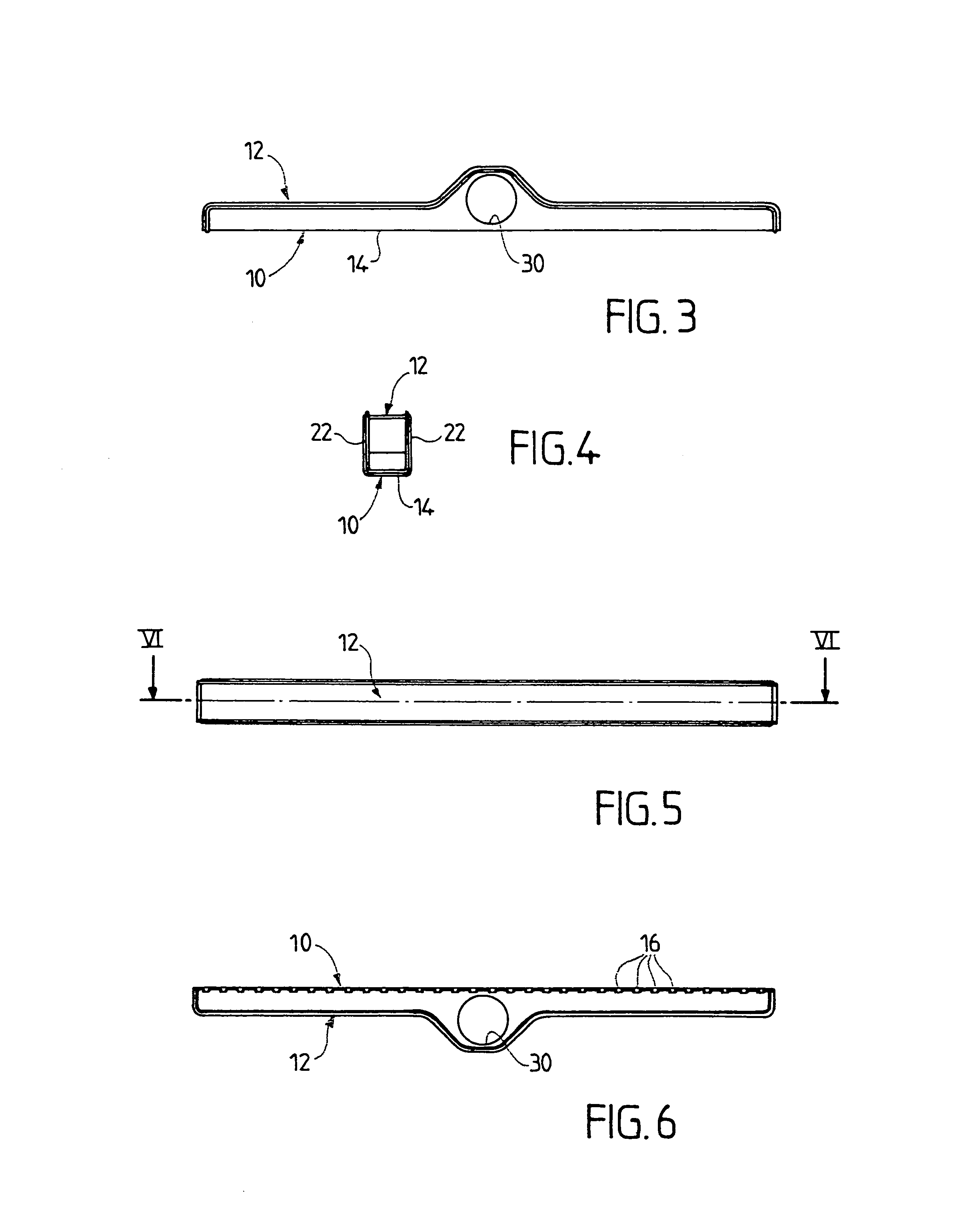
[0049]The embodiment of FIGS. 1 to 7 will be referred to first of all, in which the manifold comprises a first part 10 and a second part 12 each formed from a metal sheet, advantageously of aluminum, which is shaped by conventional cutting-out and stamping operations.

[0050]The first part 10 includes a bottom 14 which is generally flat and of elongate rectangular shape. This bottom 14 is intended to constitute the manifold plate, also called “hole plate”, of the manifold. This bottom, to that end, includes a plurality of spaced holes 16 of elongate shape intended to accommodate tubes 18 forming part of a heat-exchanger core (FIGS. 1 and 2). In the example, these are flat tubes between which are arranged fins 20 produced in the form of corrugated spacers.

[0051]The sheet 10 further comprises two lateral walls 22 folded face-to-face, which are generally flat and parallel to each other. ...


PUM


Abstract

A manifold for, e.g. a motor vehicle heat exchanger, has a first part formed from a shaped metal sheet and bottom and two lateral walls folded face-to-face, at least one of which is provided with an aperture for fixing a pipe there. A second part is shaped metal sheet and able to be fitted onto the lateral walls of the first part to form a cover opposite the bottom of this first part. Either the first part or the second part has a manifold plate. The first part, the second part and the pipe are assembled by brazing.

Description

[0001]This is a Continuation Application of U.S. patent application Ser. No. 09 / 791,644 filed on Feb. 26, 2001 now abandoned. The disclosure of the prior application is hereby incorporated by reference herein in its entirety.FIELD OF THE INVENTION[0002]The invention relates to heat exchangers, especially for motor vehicles, and more particularly to a manifold for a heat exchanger, comprising a manifold plate closed by a wall in such a way as to delimit a chamber into which at least one pipe opens out.BACKGROUND OF THE INVENTION[0003]In a manifold of this sort, the manifold plate, which is also called hole plate, possesses a multiplicity of holes in which are accommodated the extremities of tubes which constitute the core of the heat exchanger. Fins contributing to increasing the heat-exchange surface area are associated with these tubes.[0004]The manifold plate is closed by a wall so as to delimit a chamber which communicates with the tubes in order to allow a fluid to circulate in ...

Claims


Application Information

Patent Timeline
IPC IPC(8): F28F9/02F28D1/00F28F1/24B21D53/02F28F9/04F28F9/18F28F9/26
CPCF28F9/0224F28F9/0246F28F2009/029
Inventor AVEQUIN, STEPHANEMARTINS, CARLOS
Owner VALEO THERMIQUE MOTEUR
Why Eureka
Try Eureka