Universal ergonomic support with self-contained actuator

a self-contained actuator and universal technology, applied in the direction of movable seats, chairs, transportation and packaging, etc., can solve the problems of increasing the cost of materials, increasing the likelihood of component failure, shortening the life of the device, etc., to improve durability and useability, facilitate and streamline the manufacture of the device, and reduce production costs

Inactive Publication Date: 2006-07-18
L & P PROPERTY MANAGEMENT CO
View PDF145 Cites 9 Cited by
  • Summary
  • Abstract
  • Description
  • Claims
  • Application Information

AI Technical Summary

Benefits of technology

[0013]It is an object of the present invention that it use a relatively small number of moving parts which are simple in design and movement.
[0014]It is a further object of the present invention that it be compact in size for ease of packaging and ease of incorporation into a variety of different seats, automobile seats and incorporatable at various positions and in various orientations.
[0015]It is a further object of the present invention that it be economical to manufactue, sell, assemble, maintain and operate.
[0018]It is a further object of the present invention that it be able to tolerate excessive or abusive loads.
[0019]It is a further object of the present invention to ease and streamline the manufacture of the device and of seats incorporating the device, to lower production costs and increase durability and useable life of the device and seats incorporating it.
[0020]It is a further object of the present invention that it may be incorporated easily with existing components, as, for example, seat frames or headrests, and with future seats which may have less space available within them.

Problems solved by technology

The multiplicity of moving parts in prior art lumbar supports complicates manufacture, increases expense of materials necessary, increases the likelihood of component failure and shortens the life span of the devices.
Moreover, prior art lumbar supports require a relatively large amount of space to, accommodate the relatively cumbersome tensioning or compression apparatuses, together with the frameworks necessary for their support.
Accordingly, prior art devices are generally limited in their applications in that it is difficult to convert their component orientation for support of other parts of the human body in a seat, as, for example, the head and neck or the thighs.
As seat designs are modified to incorporate more comfort devices, such as duct work for heating and cooling, the amount of space available inside seats for lumbar support devices shrinks.

Method used


Image

  • Universal ergonomic support with self-contained actuator
  • Universal ergonomic support with self-contained actuator
  • Universal ergonomic support with self-contained actuator

Examples


Embodiment Construction

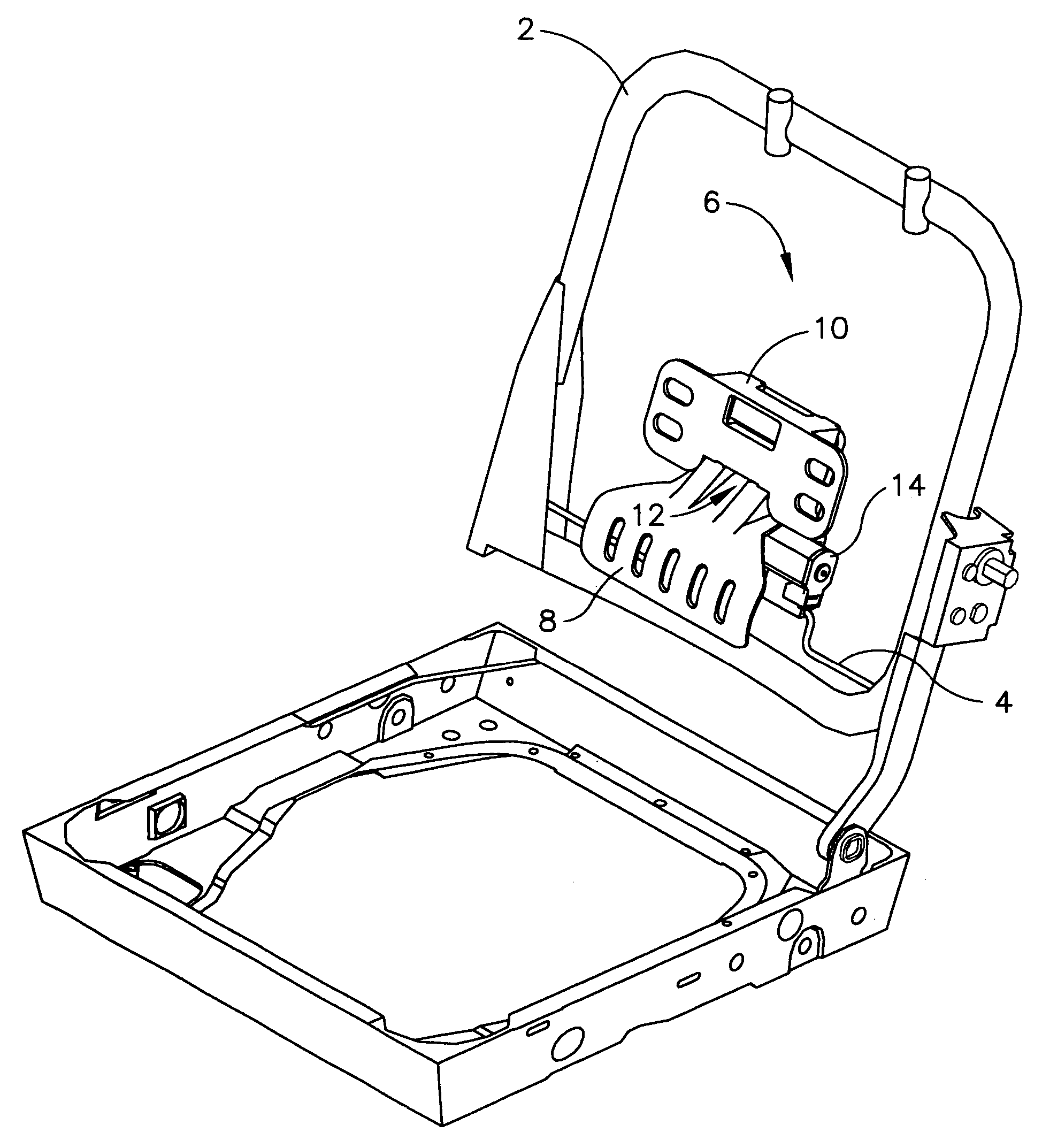
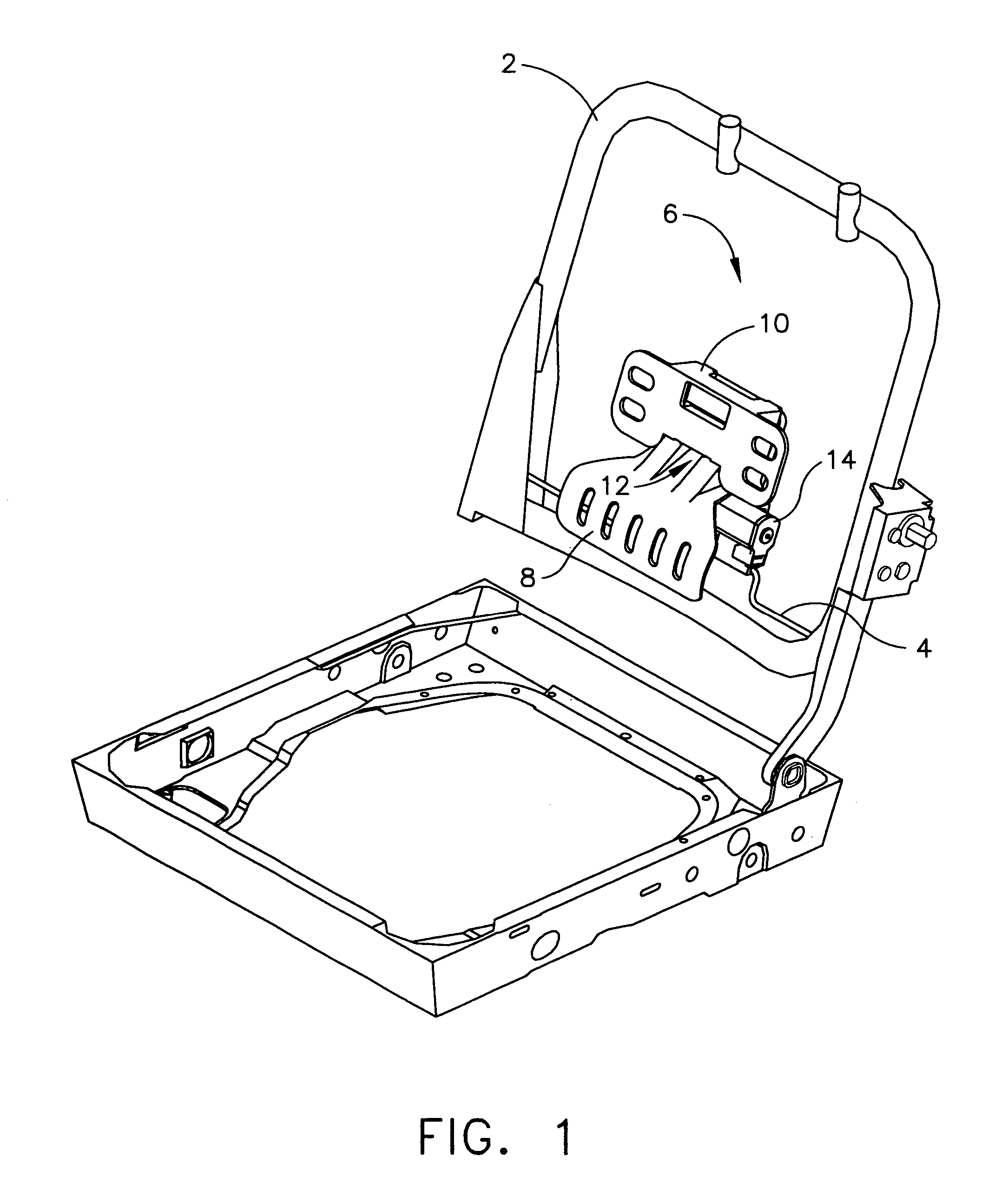
[0044]Referring to the accompanying drawings in which like reference numbers indicate like elements, FIG. 1 is an oblique view of the device of the present invention incorporated in a seat as a low apex lumbar support. Seat back frame, 2, supports an optional wire mount, 4, for the support device of the present invention, 6. Pressure surface, 8, is rotateably / slideably connected to device housing, 10, at port, 12. Engagement of motor, 14, moves pressure surface, 8, outward towards the lumbar spine of a person sitting in the seat.

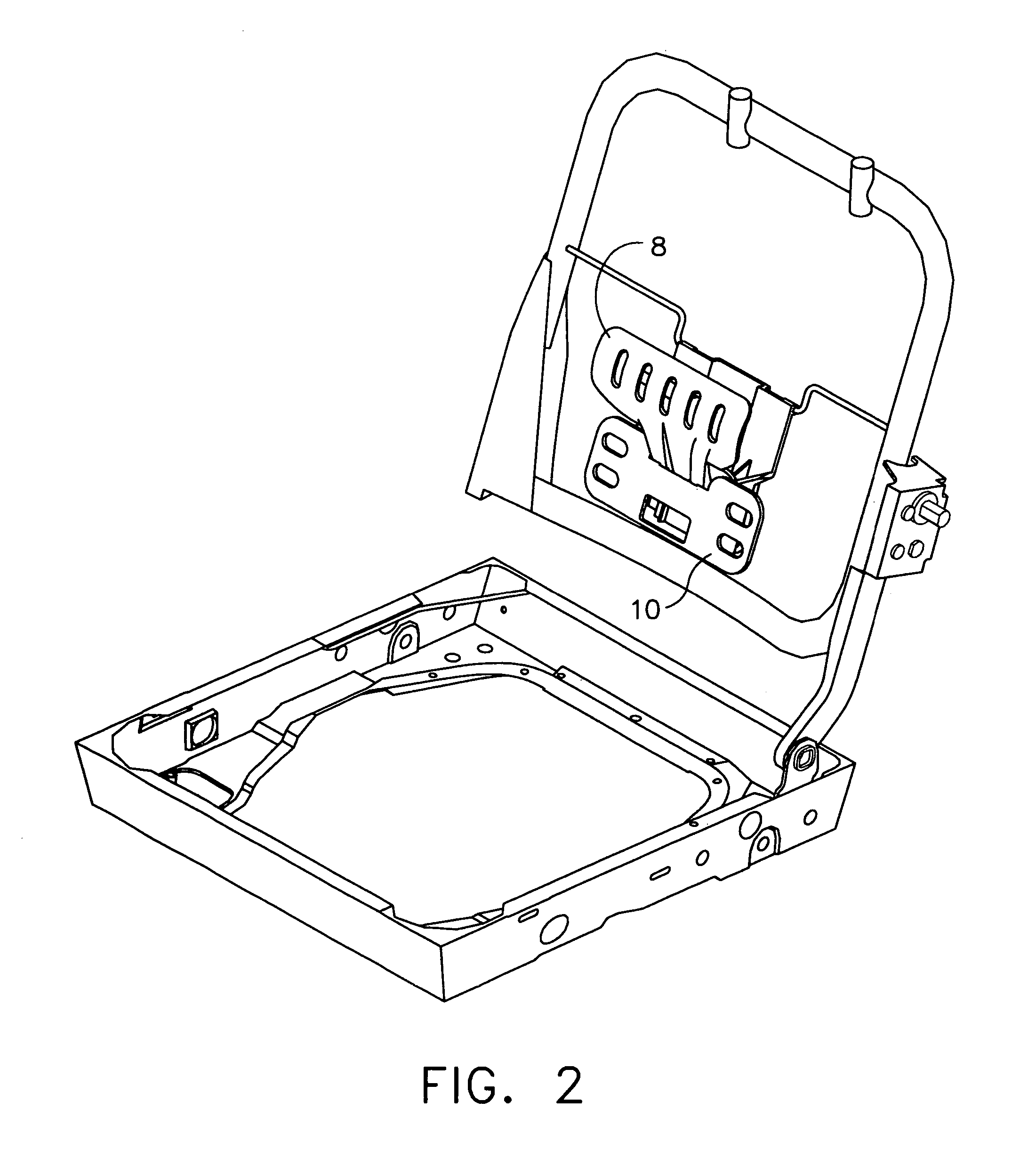
[0045]FIG. 2 depicts the support device of the present invention in a high apex position. Here, the device is simply mounted upside down, relative to the orientation depicted in FIG. 1. The pressure surface, 8, and device housing, 10, are inverted.

[0046]FIG. 3 depicts the support device of the present invention used as a neck support. Device housing, 10, is fixedly attached to seat back frame, 2, at mounts, 16. Optionally, the device may be mounted on slidea...


PUM


Abstract

An ergonomic weight support device for a seat comprising a housing having a channel defined by at least one guide boss, an extending element having an unanchored weight supporting end and an engaged end slidingly disposed within the channel of said housing and an actuator fixedly attached to said housing and in moving communication with said extending element whereby said actuator mediates the weight supporting end of said extending element between a substantially retracted position and an extended position.

Description

CROSS-REFERENCE TO RELATED APPLICATIONS[0001]This application is a continuation of non-provisional patent application Ser. No. 10 / 407,883 filed on Apr. 4, 2003, (now U.S. Pat. No. 6,824,214 B2) which is a continuation of non-provisional patent application Ser. No. 09 / 798,657 filed Mar. 1, 2001 (now U.S. Pat. No. 6,619,739).STATEMENT REGARDING FEDERALLY SPONSORED RESEARCH OR DEVELOPMENT[0002]Not ApplicableAPPENDIX[0003]Not ApplicableBACKGROUND OF THE INVENTION[0004]1. Field of the Invention[0005]This invention relates generally to ergonomic weight support devices, for seats.[0006]2. Related Art[0007]Lumbar supports and head rests for seats, particularly automobile seats, are known. See U.S. Pat. Nos. 5,050,930; 5,397,164; 5,498,063; 5,626,390; 5,775,773; 6,003,941; 4,354,709; 4,452,485; 4,632,454; 4,880,271; GB 2013 487A and D 169 293 B1. These devices all have in common one or more flexible members that may be flexed in order to create a convex surface with its apex towards the lumb...

Claims


Application Information

Patent Timeline
Patent Type & Authority Patents(United States)
IPC IPC(8): A47C7/46A47C7/14B60N2/02B60N2/48B60N2/62B60N2/66B60N2/90
CPCA47C7/462B60N2/0232B60N2/66B60N2/48B60N2/62B60N2/449B60N2/80B60N2/02246
Inventor MCMILLEN, ROBERT JAMES
Owner L & P PROPERTY MANAGEMENT CO
Why Eureka
Try Eureka