Battery connecting plate, and attachment structure of the same

a technology of connecting plate and battery, which is applied in the direction of cell component details, cell component connections, cell components, etc., can solve the problems of difficulty in adjusting the size tolerance of batteries, cracks may occur in the soldered portion, and the soldered portion may be peeled off, so as to improve the battery size tolerance can be easily and accurately mounted, and the effect of improving the efficiency of the battery assembling process

Active Publication Date: 2006-07-18
YAZAKI CORP +1
View PDF5 Cites 53 Cited by
  • Summary
  • Abstract
  • Description
  • Claims
  • Application Information

AI Technical Summary

Benefits of technology

[0031]With this arrangement, when the batteries are electrically connected by the bus bar, the size tolerance of the batteries is positively compensat d by the bus bar. Therefore, each of the batteries is easily and accurately mounted on the...

Problems solved by technology

In such a structure, it is difficult to compensate the size tolerances for batteries when the connection work is performed.
Furthermore, since an electronic el...

Method used


Image

  • Battery connecting plate, and attachment structure of the same
  • Battery connecting plate, and attachment structure of the same
  • Battery connecting plate, and attachment structure of the same

Examples


first embodiment

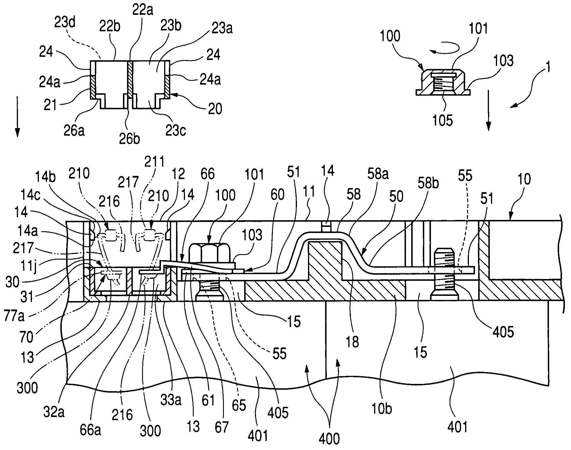
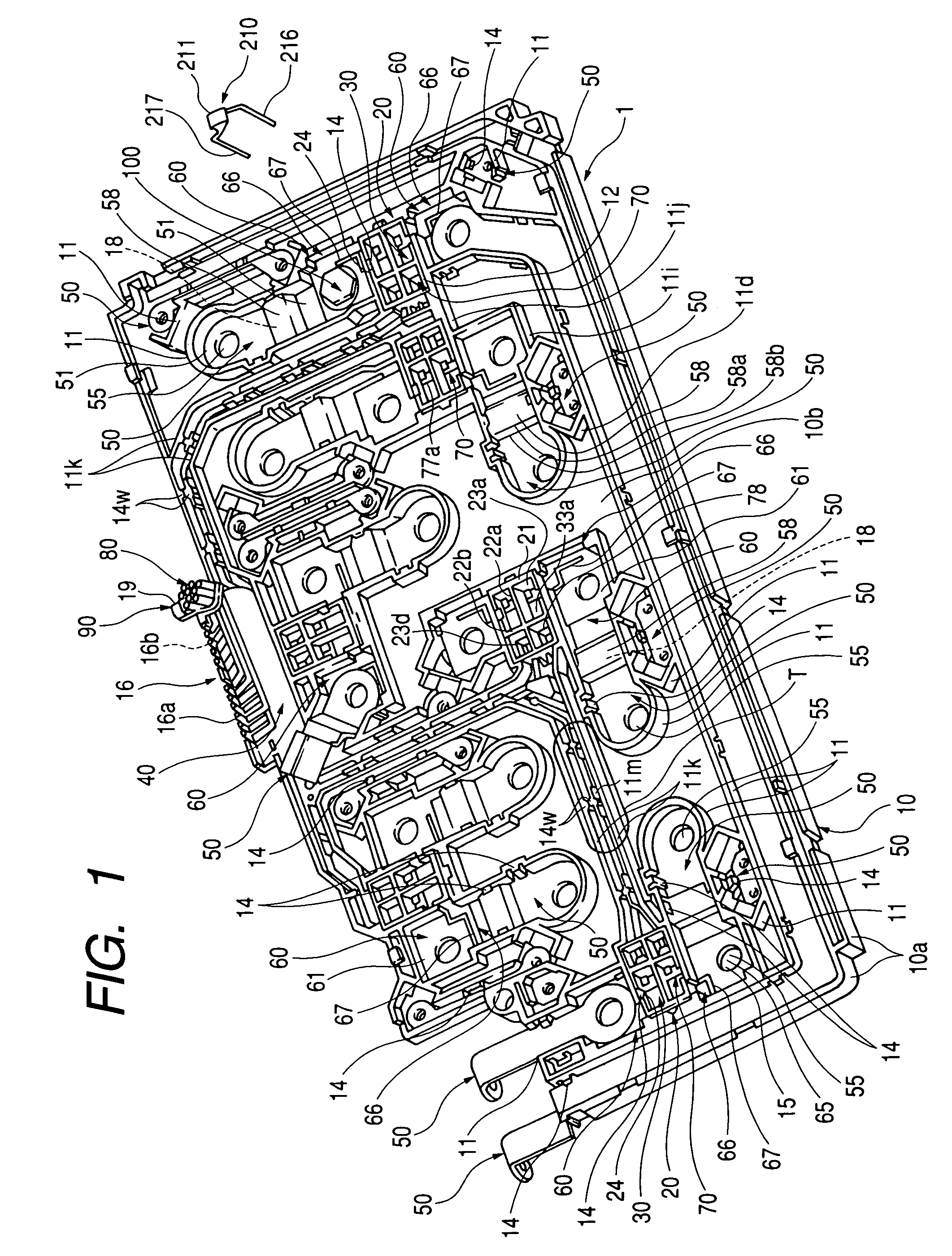
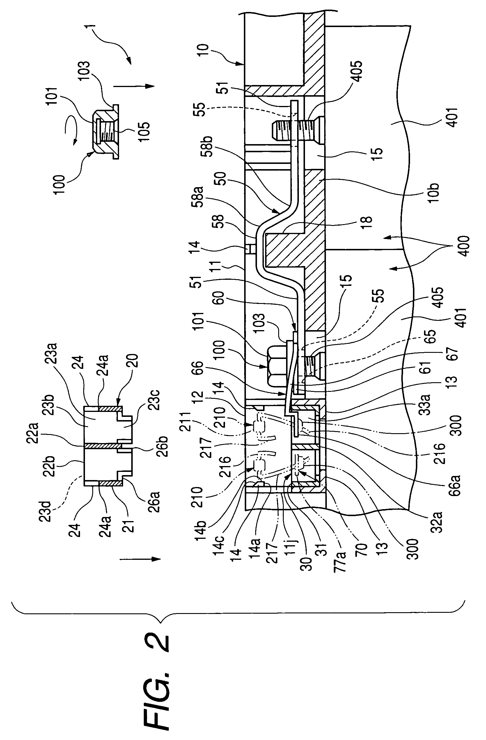
[0043]In these figures, the battery connecting plate 1 roughly comprises the plate body 10 which is mounted on batteries 400 that are arranged both vertically and horizontally; terminals 60 which are mounted on the plate body 10 and electrically connect batteries 400 and electronic elements 210; and upper covers 20 and lower covers 30 which are used to attach the terminals 60 to the plate body 10.

[0044]The vertical size tolerance of the thus arranged batteries 400 is defined as being about ±0.1 mm. In order to assemble these batteries 400 into a single unit, the plate body 10 is attached to these batteries 400.

[0045]The plate body 10 includes the base wall 10b; a upright peripheral wall 10a formed around the outer edge of the base wall 10b; and upright guide walls 11, 11i, 11j, 11k and 11m formed on the base wall 10b. These members are integrally formed by using a synthetic resin material.

[0046]Metallic bus bars 50, which are plated with tin in order to provide improved anticorrosi...

third embodiment

[0084]Instead of the continuous guide walls 11k provided in an encircled area T in FIG. 1, as the invention, guide walls 111k shown in FIG. 6 may be employed. In this case, the guide walls 111k are partially removed and the guide walls 111k are discretely arranged. With this arrangement, the guide walls 11k and 111k are separately provided by defining spaces 11n therebetween, so that the power lines 80 can be easily laid for the plate body 10. Holes 11p are formed to permit the insertion of a tool for forming the retainers 14w.

[0085]As shown in FIG. 6, each of the power lines 80 includes a conductor 81 formed by coiling soft copper lines, and an insulating sheath 82 of vinyl chloride for protecting the conductor 81. Furthermore, as shown in FIG. 1, the twelve collected power lines 80 are folded at a pectinated portion 16. The pectinated portion 16 is formed with projections 16a defining twelve grooves 16b therebetween which are associated with the twelve power lines 80.

[0086]A synt...


PUM


Abstract

A plate body is disposed on a plurality of arrayed batteries. A first terminal is provided with a first portion which is connected to one of the batteries, and a second portion which is connected to an electronic element. A cover member is attached onto the plate body in a first direction, to provisionally fix the first terminal on the plate body. The first terminal is provided with a tolerance compensator, which connects the first portion and the second portion while compensating a positional difference between the first portion and the second portion in the first direction.

Description

BACKGROUND OF THE INVENTION[0001]The present invention relates to a battery connecting plate for connecting batteries mounted in an electric vehicle, and relates to an attachment structure of the same.[0002]FIG. 7 shows a related-art battery connecting plate disclosed in Japanese Patent Publication No. 2000-333343A.[0003]In a battery connecting plate 501, a terminal 505 and a bus bar 509 are insertion-molded with a plate body 502. The terminal 505 is screwed to the electrode of a battery. Also attached to the plate body 502 are pivotable covers 504.[0004]In such a structure, it is difficult to compensate the size tolerances for batteries when the connection work is performed. If the terminal 505 is used to compensate such size tolerance, a crack may occur in the terminal 505. Furthermore, since an electronic element is soldered to an element mounting portion 510 of the terminal 505, either the soldered portion may be peeled off or a crack may occur in the soldered portion.SUMMARY OF...

Claims


Application Information

Patent Timeline
IPC IPC(8): H01R24/00H01R33/00H01M50/503H01R4/18H01R11/28H01R13/426H01R13/631H01R13/66H01R13/68
CPCH01M2/206H01R11/283H01R11/287H01R11/288H01R4/183H01R2201/26H01R13/426H01R13/6315H01R13/6616H01R13/68Y02E60/10H01M50/503
Inventor IKEDA, TOMOHIROSAITO, KAZUAKI
Owner YAZAKI CORP
Why Eureka
Try Eureka