
Flow-through conductivity sensor

a conductivity sensor and flow-through technology, applied in the field of flow-through conductivity sensors, can solve the problems of driving up manufacturing costs and different sizes of toroids, and achieve the effect of improving the flow-through conductivity sensor

Inactive Publication Date: 2006-07-18
ROSEMOUNT ANALYTICAL
View PDF18 Cites 28 Cited by
  • Summary
  • Abstract
  • Description
  • Claims
  • Application Information

AI Technical Summary

Problems solved by technology

One limitation of such sensors, however, has been that when sensors are offered for different pipe sizes, different sized toroids must be manufactured to accommodate the various pipe sizes.
This tends to drive up manufacturing costs since the individual lots of toroids are relatively smaller.

Method used


Image

  • Flow-through conductivity sensor
  • Flow-through conductivity sensor
  • Flow-through conductivity sensor

Examples


Embodiment Construction

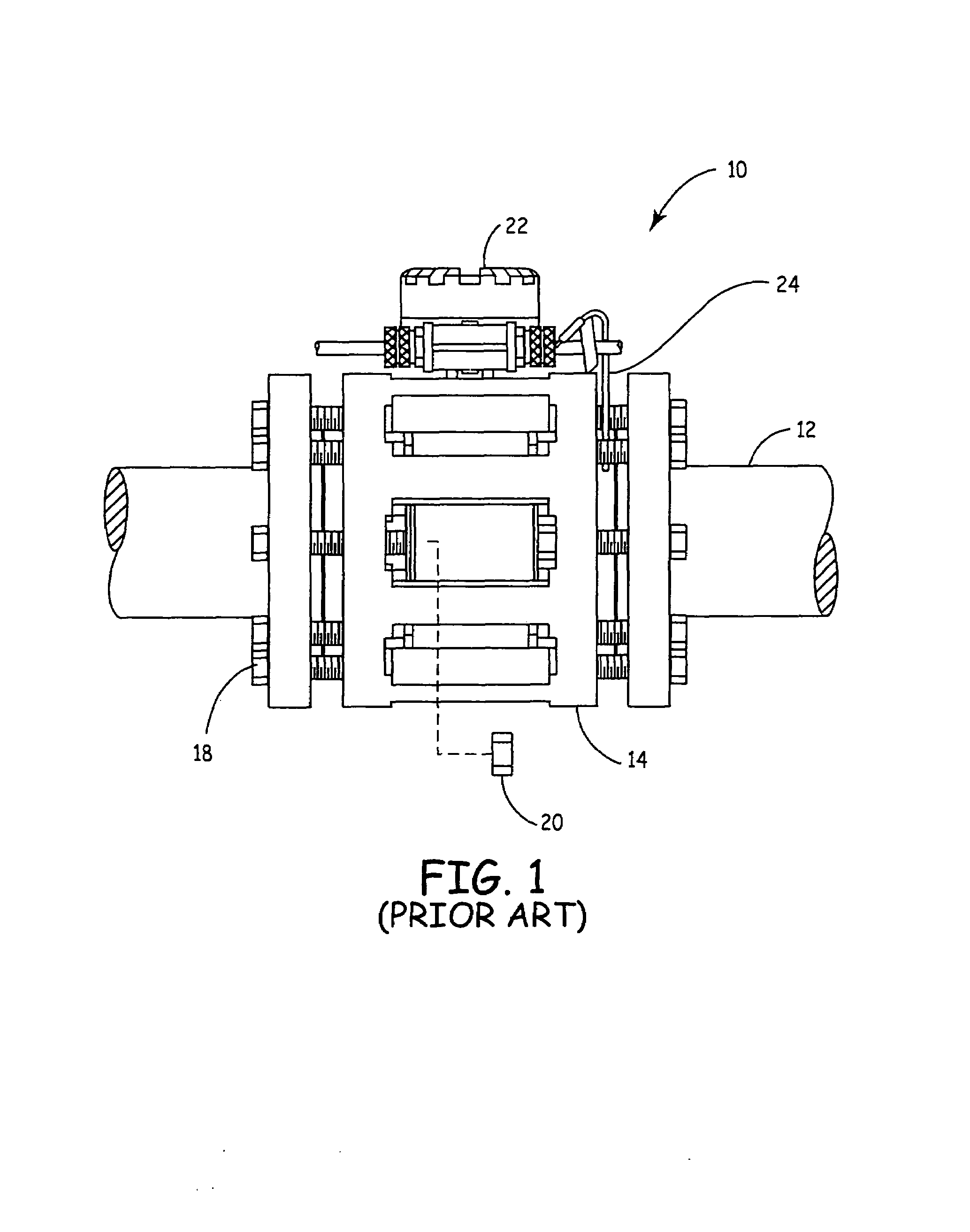
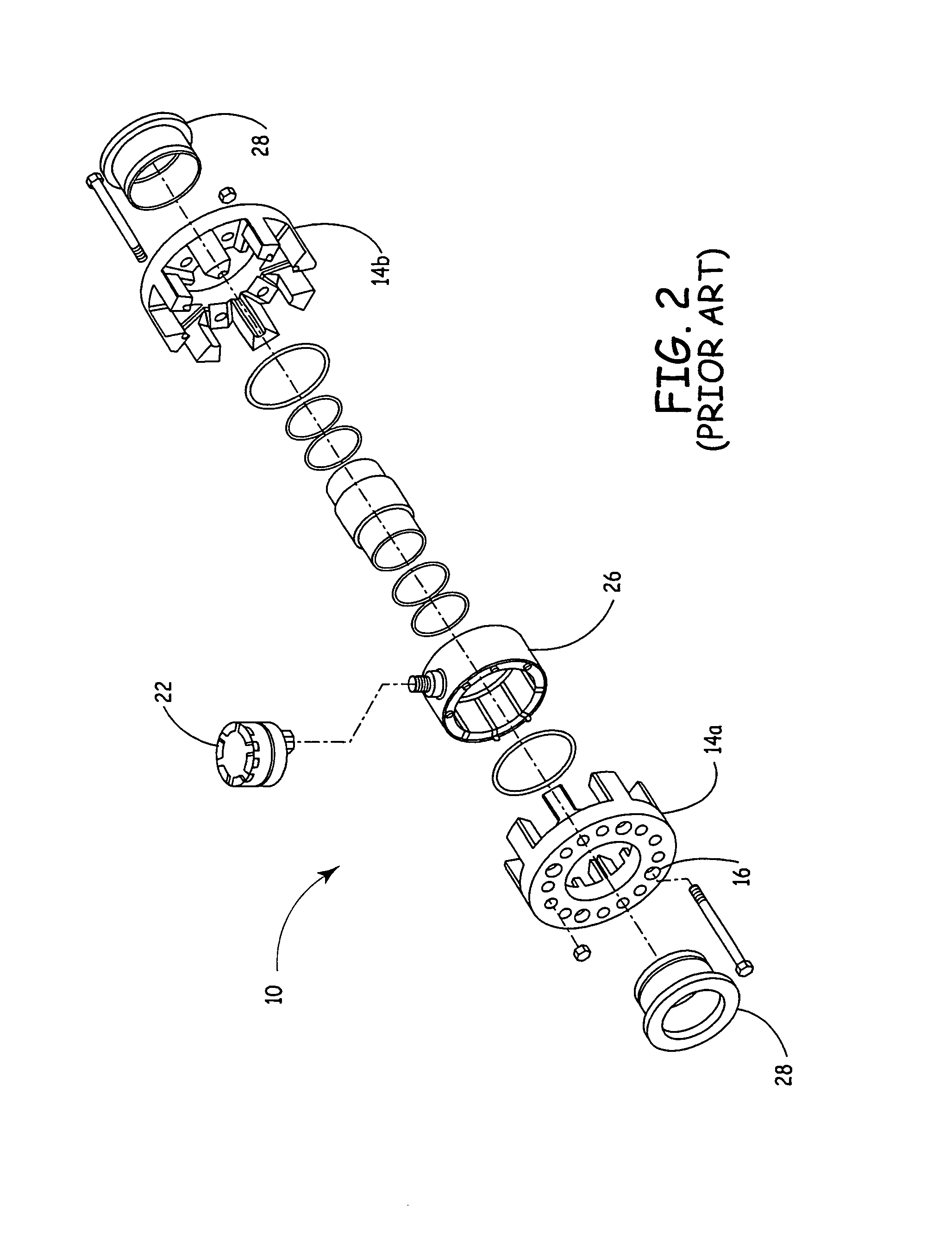
[0014]FIGS. 1 and 2 are side elevation and perspective views, respectively, of a flow-through conductivity sensor in accordance with the prior art. Sensor 10 is adapted to mount to process piping 12 in order to measure conductivity of process fluid flowing therethrough. Sensor 10 includes body 14 which is generally a two-part construction from halves 14a and 14b (illustrated in FIG. 2). A number of holes 16 within each of the halves 14a, 14b are sized to receive mounting bolts 18 and allow the body to be fixed to pipe flanges using mounting bolts 18 and suitable fasteners 20. Junction box 22 is generally fixed to the top of sensor 10 and includes any suitable wiring terminations and connections, as may be appropriate. Since it is generally known that conductivity can vary as a function of temperature, sensor 10 generally includes a temperature sensitive device 24 that is adapted to provide an indication of process fluid temperature flowing through sensor 10 such that the conductivit...


PUM

PropertyMeasurementUnit
conductivityaaaaaaaaaa
electrical currentaaaaaaaaaa
conductanceaaaaaaaaaa

Abstract

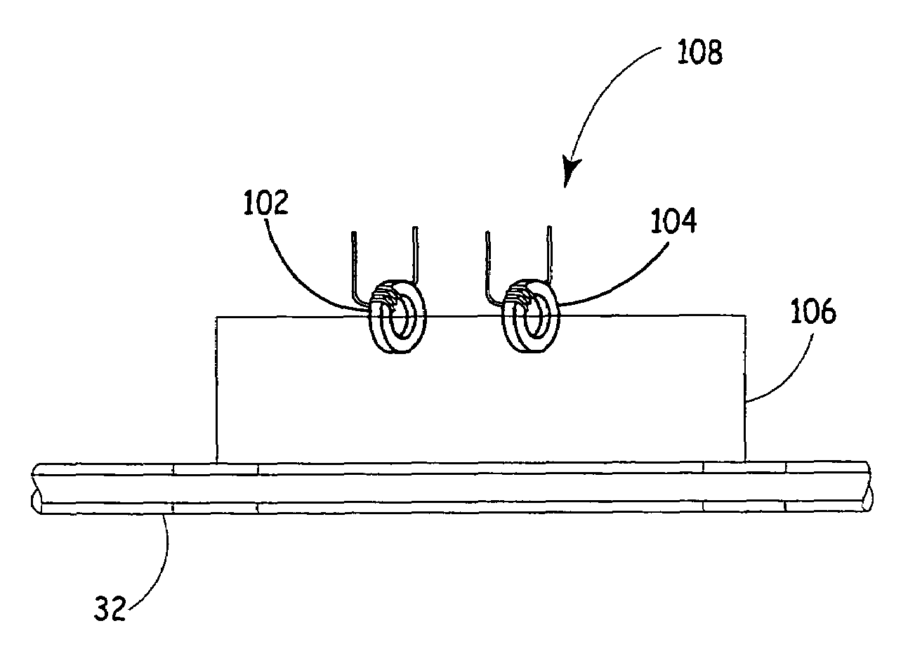
An improved flow-through conductivity sensor is provided. The sensor includes a current return path that has a current return conductor. At least one toroid of the sensor is removed from the flow path and configured to interact with the current return conductor to provide an indication of conductivity. Additional aspects of the invention include disposing a pair of toroids about the current return conductor; disposing a toroid about the current return conductor and configuring the toroid as a transformer.

Description

FIELD OF THE INVENTION[0001]The present invention is related to devices and systems that measure conductivity. More particularly, the present invention relates to flow-through type conductivity sensors.BACKGROUND OF THE INVENTION[0002]Conductivity measurement sensors are well known in the art and are used to measure the conductivity of a fluid, such as a liquid or a dispersion of solids suspended in a liquid. Conductivity sensors are often used to investigate the properties of electrolytes in solution, such as the degree of disassociation, the formation of chemical complexes, and hydrolysis. The conductivity of a fluid may also be used to measure a wide variety of other parameters, such as the amount of contaminants in drinking water and a measure of chemical concentrations in industrial process streams. Applications such as these involve the determination of conductivities in many different physical environments.[0003]Toroidal conductivity sensors generally include two toroidal coi...

Claims


Application Information

Patent Timeline
Patent Type & Authority Patents(United States)
IPC IPC(8): G01N27/08G01R15/18G01F1/64G01N27/02G01N27/07G01R27/22
CPCG01N27/023G01R27/22G01N27/07
Inventor FENG, CHANG-DONGBENTON, BARRYREZVANI, BEHZAD
Owner ROSEMOUNT ANALYTICAL
Learn More