
Bayonet coupling mechanism for a centrifuge

a technology of centrifuge and coupling mechanism, which is applied in the direction of coupling, rod connection, centrifuge, etc., can solve problems such as damage to the machin

Inactive Publication Date: 2006-07-25
KENDRO LAB PRODS
View PDF46 Cites 53 Cited by
  • Summary
  • Abstract
  • Description
  • Claims
  • Application Information

AI Technical Summary

Benefits of technology

[0014]In accordance with still another embodiment of the present invention, a centrifuge is provided having a motor shaft and a rotor that engages the motor shaft. The centrifuge also includes a cover having a knob with a top surface. An indicator is disposed within knob wherein the indicator is in a first position relative to the top surface when the rotor is secured to the motor shaft. The indicator is in a second position relative to the top surface with the rotor is released form the motor shaft.
[0015]There has thus been outlined, rather broadly, the more important features of the invention in order that the detailed description thereof that follows may be better understood, and in order that the present contribution to the art may be better appreciated. There are, of course, additional features of the invention that will be described below and which will form the subject matter of the claims appended hereto.

Problems solved by technology

Damage to the machine may result if either screw is not properly tightened.

Method used


Image

  • Bayonet coupling mechanism for a centrifuge
  • Bayonet coupling mechanism for a centrifuge
  • Bayonet coupling mechanism for a centrifuge

Examples


Embodiment Construction

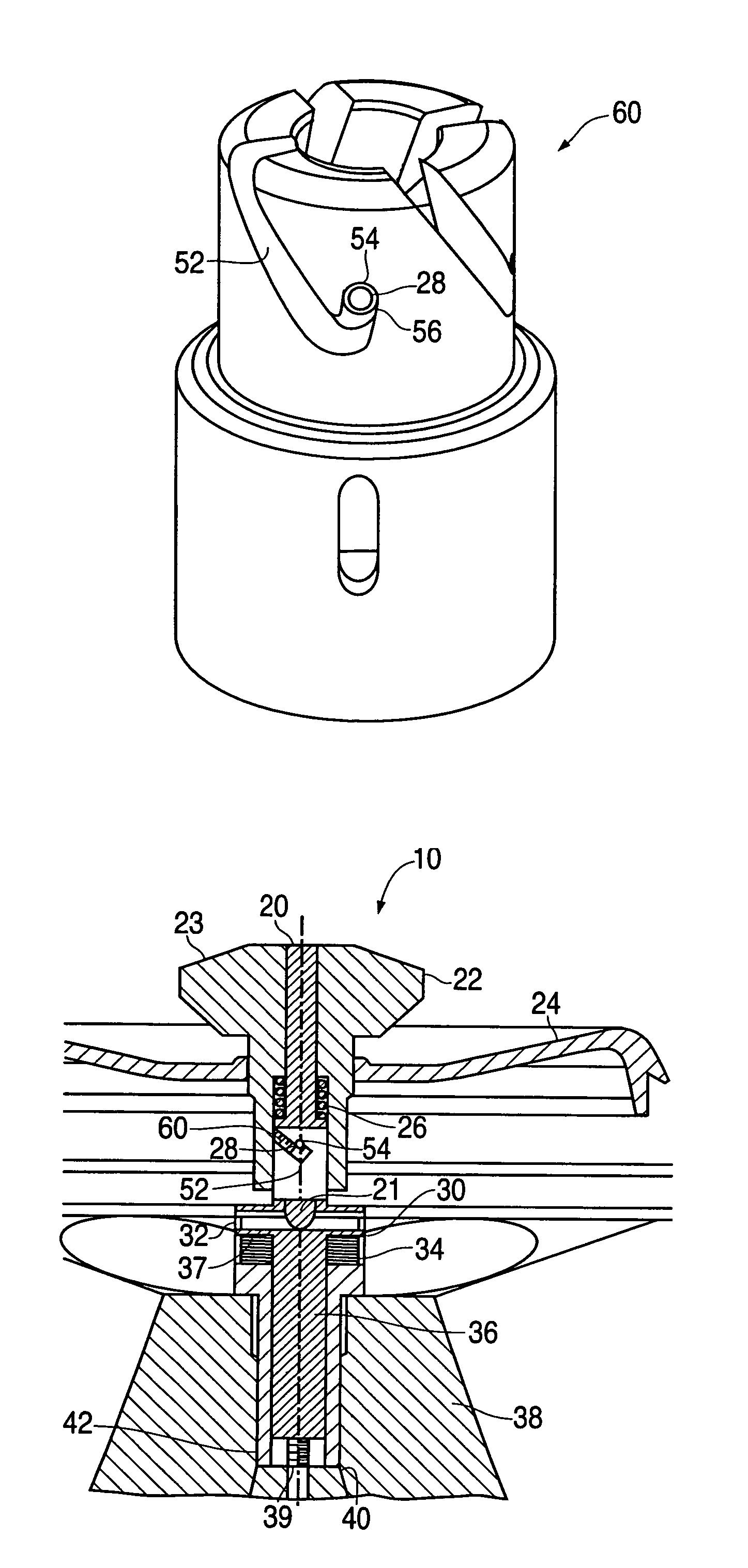
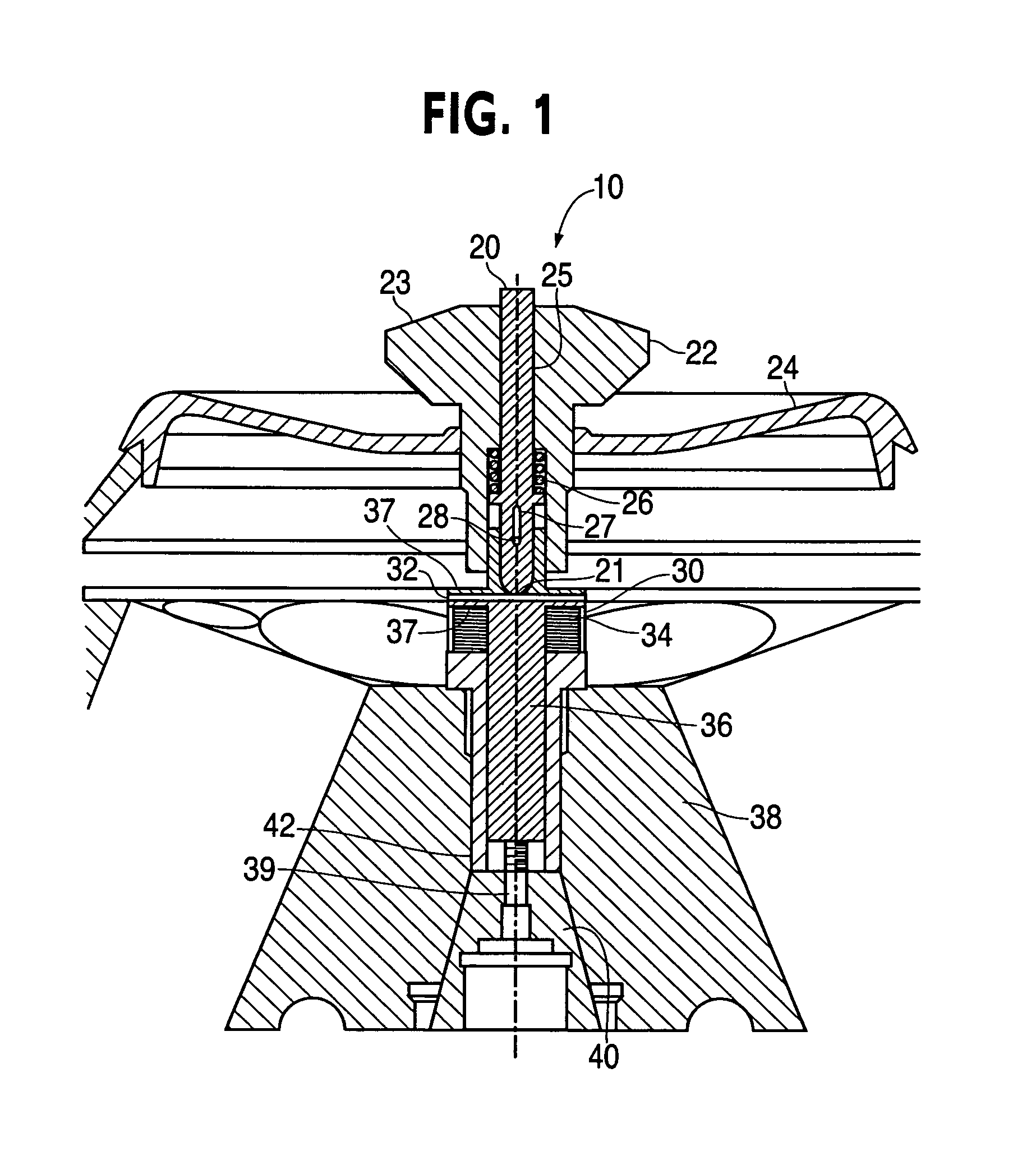
[0023]The present invention can best be described by reference to the attached figures, wherein FIG. 1 is a side plan cross-sectional view of a centrifuge cover assembly in the unlocked position. The centrifuge according to the present invention, generally represented by reference numeral 10, includes a motor shaft 40, a rotor body 38 and a rotor cover 24.

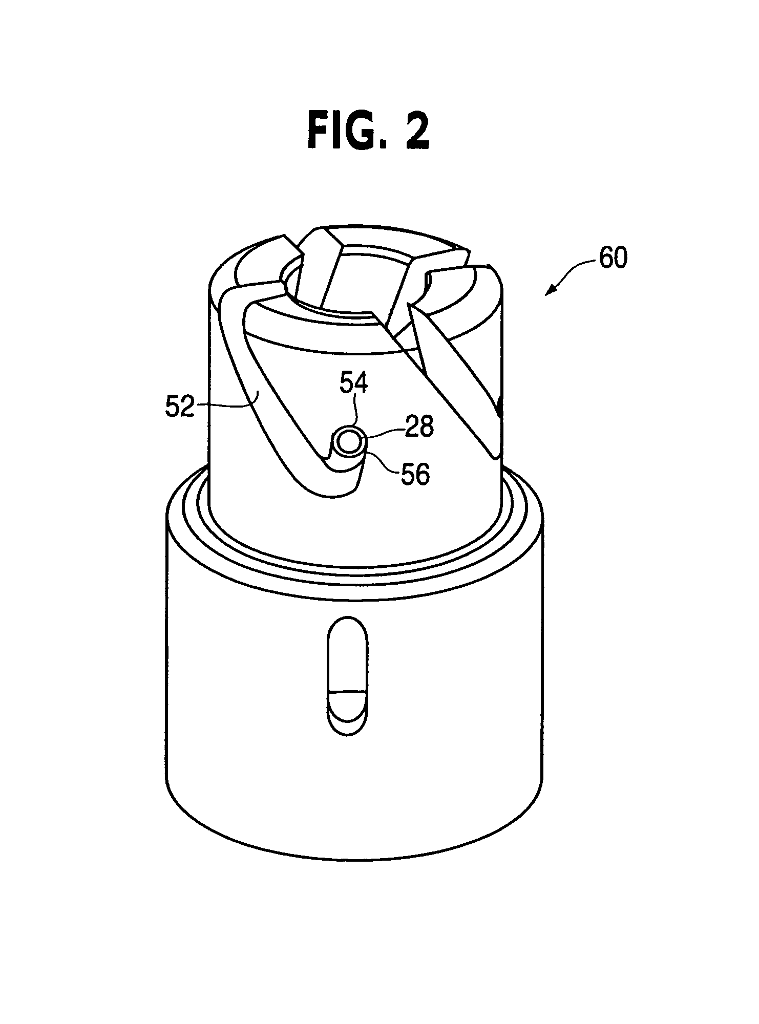
[0024]Rotor body 38 houses a shaft pin 32, a rotor drive adapter 42, an outer housing 30, having biasing elements 34 such as bevel spring washers, disposed therein, and a rotor hold down shaft 36. Rotor hold down shaft 36 has a flanged end 37 and a threaded end 39. Rotor cover 24 includes a rotor knob 22 with a top surface 23 and having a inner bore or channel 25, a rotor tighten-down indicator pin 20 with a tapered end 21, a knob pin 28 disposed in the lower portion of rotor tighten-down indicator pin 20, and a biasing element, such as coil spring 26.

[0025]Rotor body 38 is secured to motor shaft 40, and rotor cover 24 is secured t...


PUM

PropertyMeasurementUnit
densityaaaaaaaaaa
drive torqueaaaaaaaaaa
rotational speedsaaaaaaaaaa

Abstract

A centrifuge having a motor shaft, a rotor that engages the motor shaft and a cover for securing the rotor to the rotor shaft. The cover has a knob with a coupling disposed therein. The coupling functions to simultaneously secure the rotor cover to the rotor body and the rotor body to the motor shaft.

Description

PRIORITY[0001]This application claims priority to the provisional U.S. patent application entitled, EASY ACCESS COVER, filed Apr. 22, 2002, having a Ser. No. 60 / 374,123, the disclosure of which is hereby incorporated by reference.FIELD OF THE INVENTION[0002]The present invention relates generally to centrifuges, and more specifically to a centrifuge cover in which a rotor tighten-down device and a cover tighten-down device are integrated into a single locking mechanism.BACKGROUND OF THE INVENTION[0003]A centrifuge is a device by which a liquid sample may be subjected to a centrifugal force, thereby separating the sample into constituent components based on the density of each component. A centrifuge rotor is a component of a centrifuge device that is adapted to hold tubes filled with the liquid sample. A centrifuge motor shaft transmits a drive torque from a motor to the rotor; thus spinning the rotor at high rotational speeds to achieve the centrifugal force required to separate th...

Claims


Application Information

Patent Timeline
Patent Type & Authority Patents(United States)
IPC IPC(8): B04B7/06B04B7/02B04B9/08
CPCB04B7/02B04B9/08Y10T29/49826B04B2009/085Y10T403/7007B04B2007/025B04B7/08
Inventor SCHUTZ, KLAUSPOTTER, RAYMOND GARY
Owner KENDRO LAB PRODS
Features
  • Generate Ideas
  • Intellectual Property
  • Life Sciences
  • Materials
  • Tech Scout
  • Unparalleled Data Quality
  • Higher Quality Content
  • 60% Fewer Hallucinations
Learn More