Software correction method and apparatus for a variable orifice flow meter

a flow meter and variable orifice technology, applied in the field of software related correction methods, can solve the problems of large flow calculation error, small change in discharge coefficient, and error in flow calculation, and achieve the effect of increasing or decreasing fluid flow

Inactive Publication Date: 2006-08-01
RIVATEK
View PDF14 Cites 10 Cited by
  • Summary
  • Abstract
  • Description
  • Claims
  • Application Information

AI Technical Summary

Benefits of technology

[0047]The software related correction methods may utilize a matrix or array of stored discharge coefficients that correlate to specific pressure differential and orifice size characteristics of the flow device. Other software related correction methods may utilize equations or algorithms to calculate an exact discharge coefficient for each determined pressure differential and orifice size of the flow device. The arrays of discharge coefficients and the equations / algorithms used to calculate discharge coefficients may be stored in memory and used by a controller, such as a processor, to determined fluid flow.

Problems solved by technology

Since the pressure differential must be accurately known to calculate the flow rate, any error in the differential pressure measurement causes an error in the flow calculation.
As the slope of the curve gets steeper at low flow rates (see FIG. 16), any pressure measurement error causes a larger flow calculation error.
However, even though computational fluid dynamics (CFD) software can be used to optimize the design of a variable-sized orifice, there is still a small change in the discharge coefficient as the size of the orifice is varied.
Although a variable orifice flow meter may have the advantage of extending the range of a flow meter by as much as a factor of 10, it may have the inherent drawback of decreased accuracy due to slight changes in the discharge coefficient at different openings, and for different flow rates at any given opening size.
In addition to the above noted disadvantages related to discharge coefficients, known variable orifice devices are ineffective for several other reasons.
First, known variable orifice devices typically use circular or curved members that are moved with respect to the fluid flow to change the size of the orifice.
Because of the curved nature of these members, the shape of the orifice changes as the size of the orifice changes, which results in significant errors when calculating the fluid flow over a range of orifice sizes.
Second, the changed shape of the orifice leads to non-ideal orifice shapes for at least a portion of the flow range.
This leads to inconsistent flow characteristics for any given opening as flow rate changes, again leading to errors in the calculation of fluid flow.

Method used


Image

  • Software correction method and apparatus for a variable orifice flow meter
  • Software correction method and apparatus for a variable orifice flow meter
  • Software correction method and apparatus for a variable orifice flow meter

Examples


Embodiment Construction

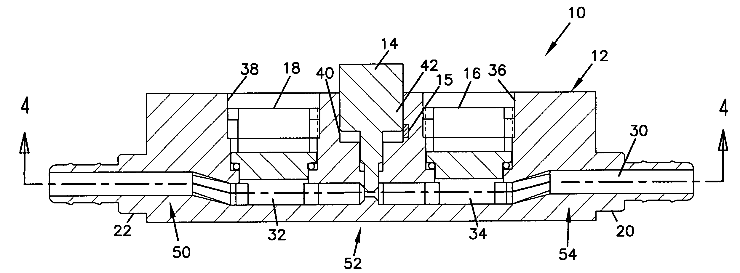
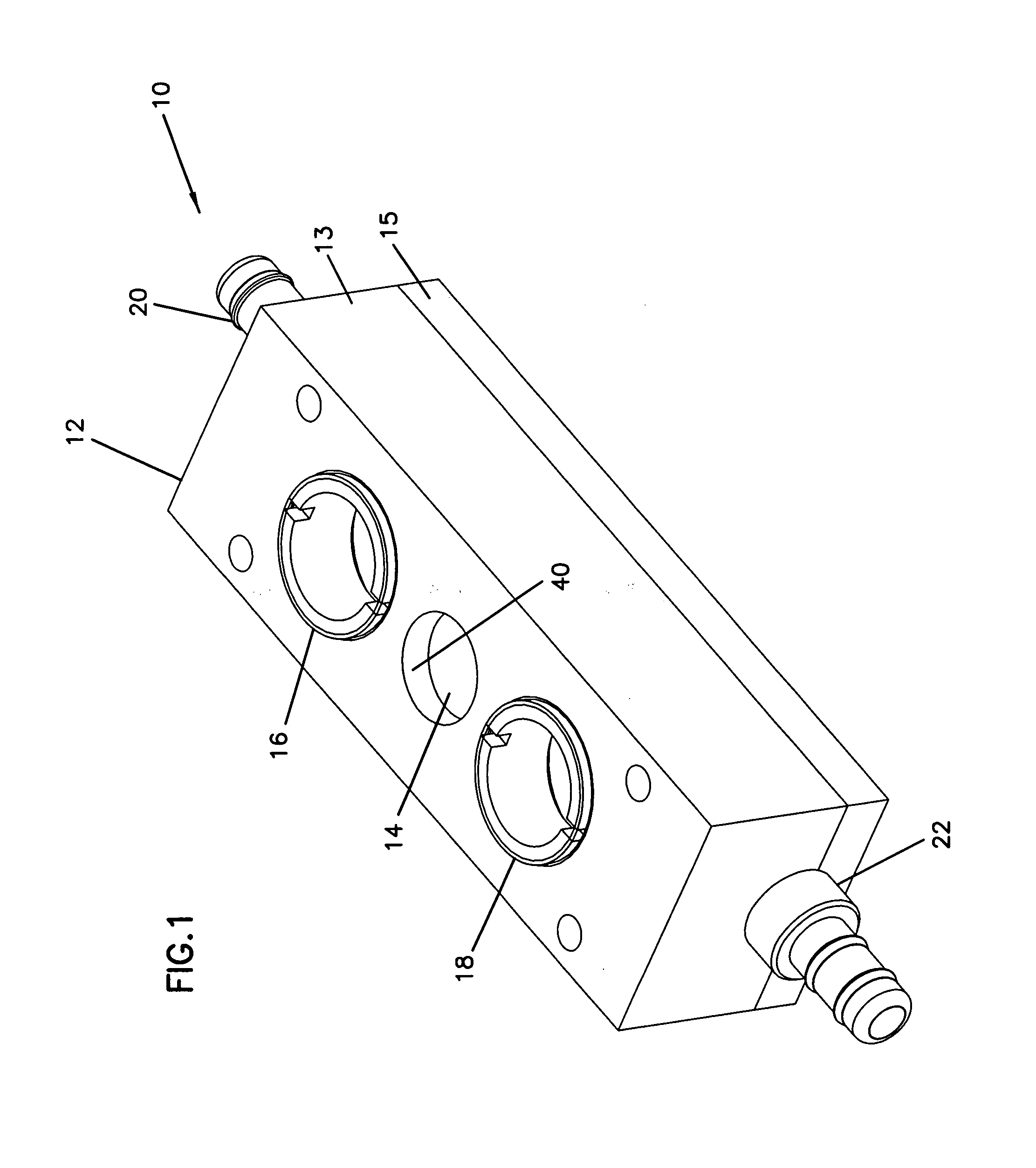
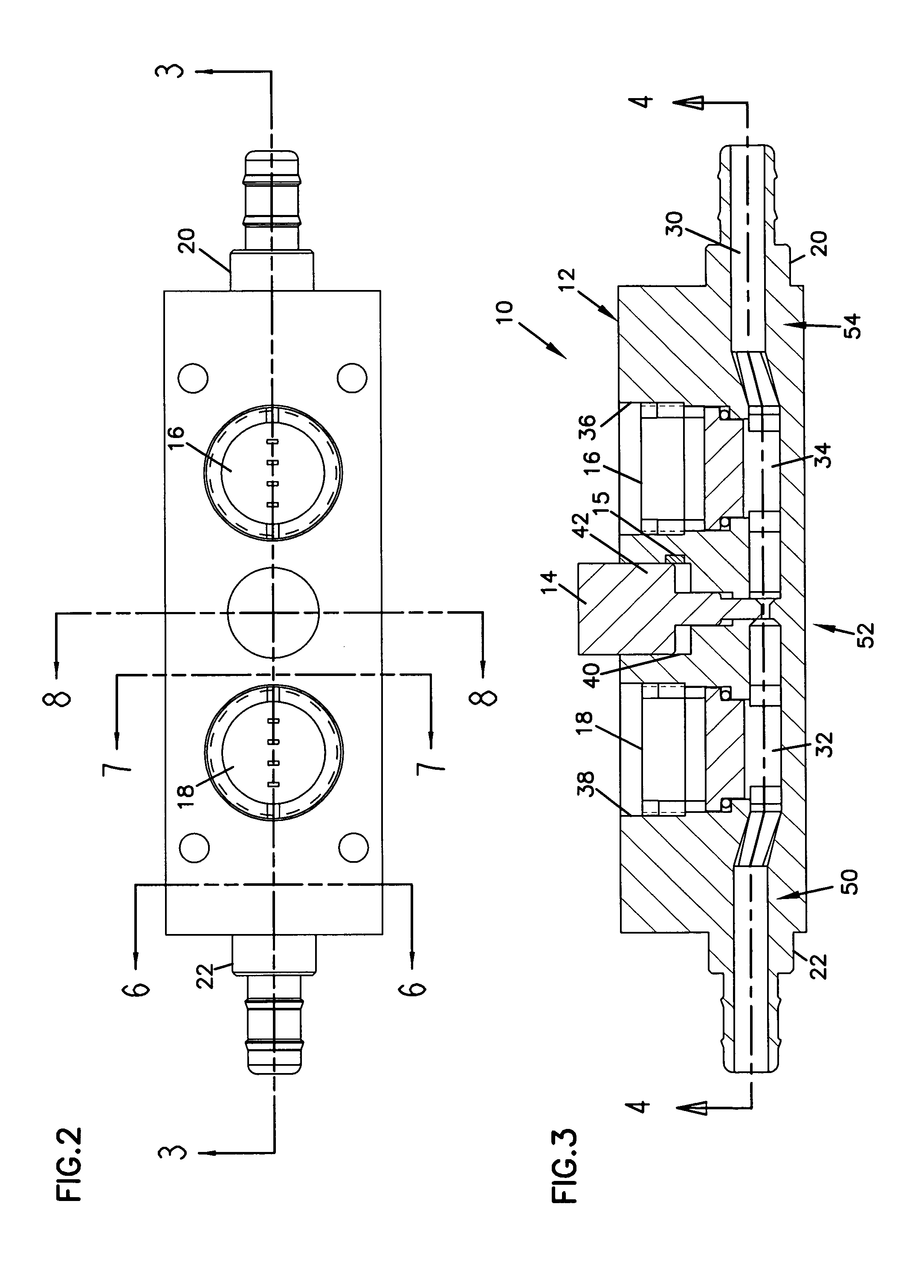
[0046]The invention generally relates to fluid flow metering and control devices, and more particularly relates to variable-sized orifice flow devices and software related correction methods for such flow devices. The variable-sized orifice may be particularly suited for use in a differential pressure flow meter as will be described herein with reference to the several drawings, although such an application is only exemplary of the many applications to which principles of the present invention may be applied.

[0047]The software related correction methods may utilize a matrix or array of stored discharge coefficients that correlate to specific pressure differential and orifice size characteristics of the flow device. Other software related correction methods may utilize equations or algorithms to calculate an exact discharge coefficient for each determined pressure differential and orifice size of the flow device. The arrays of discharge coefficients and the equations / algorithms used ...


PUM


Abstract

A method of improving the accuracy of a variable orifice flow meter that includes characterizing the discharge coefficient of the flow meter orifice for different orifice openings and for different differential pressures. The method may be particularly useful with a flow metering and controlling device that includes a fluid flow conduit having at least one planar inner wall and an element having a linear edge configured to mate with the at least one planar inner wall of the fluid flow conduit. The element is movable relative to the conduit to define a flow orifice and vary a cross-sectional area of the orifice. The device also includes a processor configured to calculate the fluid flow based on the cross-sectional area of the orifice, the differential pressure, and the discharge coefficient.

Description

BACKGROUND OF THE INVENTION[0001]1. Technical Field[0002]The present invention generally relates to fluid flow metering and control devices, and more particularly relates to software related correction methods for such flow devices.[0003]2. Related Art[0004]In process control industries, it is common to use small diameter tubes to carry process fluids at low flow rates when small amounts of fluids are required for manufacturing processes. The tubes are almost always of a circular cross-section. Instruments used to measure a flow rate in the tubes must interface with a fluid flowing in the tube while minimizing disturbance to the fluid flow. To minimize disturbance to the fluid flow, the instrument typically includes a circular cross-section to match the cross-section of the tubes. The flow rate for a flow meter measuring a change in pressure across an orifice is defined by the following Equation 1:[0005]Q=C·Ao·(11-(AoAP)2)12·(2·(Phi-Plo)ρ)12Equation⁢⁢1[0006]Where:[0007]Q=volumetric ...

Claims


Application Information

Patent Timeline
Patent Type & Authority Patents(United States)
IPC IPC(8): G01F1/22G01F1/34G01F1/42
CPCG01F1/42
Inventor KIELB, JOHN ALLANEDWARDS, GRANT BRADLEY
Owner RIVATEK
Why Eureka
Try Eureka