Baseball fielding practice machine

a fielding machine and ball technology, applied in the field of practice machines, can solve the problems of not employing a control system for adjusting parameters in most prior art pitching and ball-throwing machines, and none of the above-described prior art pitching or ball-throwing machines incorporate a control system for providing automated fielding practice for ball players

Active Publication Date: 2006-08-01
EPIC SPORTING GOODS
View PDF20 Cites 46 Cited by
  • Summary
  • Abstract
  • Description
  • Claims
  • Application Information

AI Technical Summary

Benefits of technology

[0019]The present invention practice machine can simulate practically any type of hit to substantially all locations of a practice field. Thus, the practice machine can be used to conduct a baseball fielding practice session that efficiently provides simulated hits at various trajectories to all of the player positions of the practice field.

Problems solved by technology

However, in most machines, such adjustments normally require manually adjusting the speed of wheels used to propel a ball or the angular position of a barrel of the machine.
Thus, most prior art pitching and ball-throwing machines do not employ a control system for adjusting the parameters of a ball propelled from the machine.
Although, many of the above-described prior art pitching or ball-throwing machines can be positioned to project balls to simulate ground balls, pop-ups or other types of hits for use in fielding practice for baseball players, none of the above-described prior art pitching or ball throwing machines incorporate a control system for providing automated fielding practice for ball players.
Another disadvantage associated with most prior art pitching or ball throwing machines is that most of the prior art machines do not include a scoreboard for displaying information related to a simulated game situation so that players in a fielding practice session can practice as if in a real game situation.

Method used


Image

  • Baseball fielding practice machine
  • Baseball fielding practice machine
  • Baseball fielding practice machine

Examples


Embodiment Construction

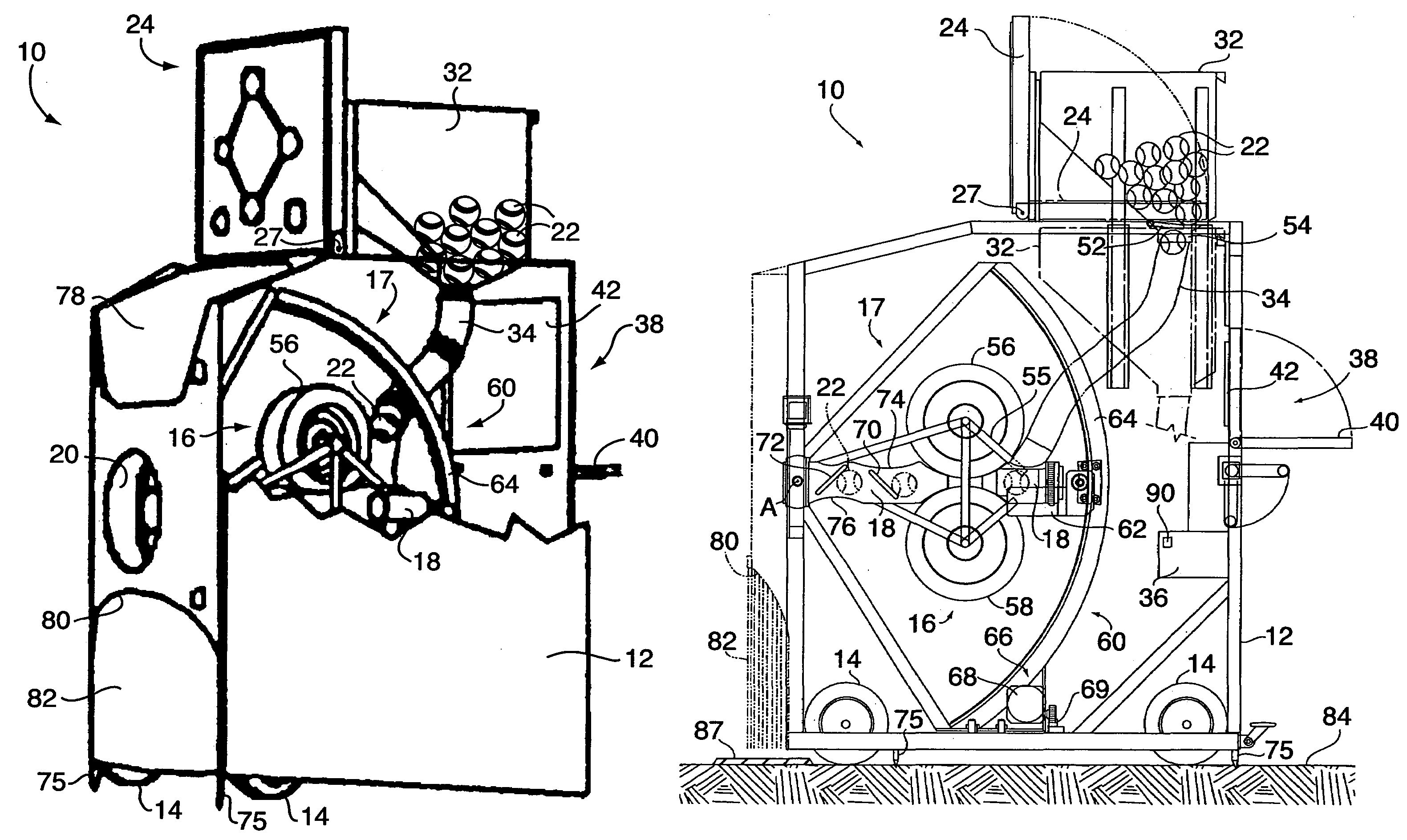
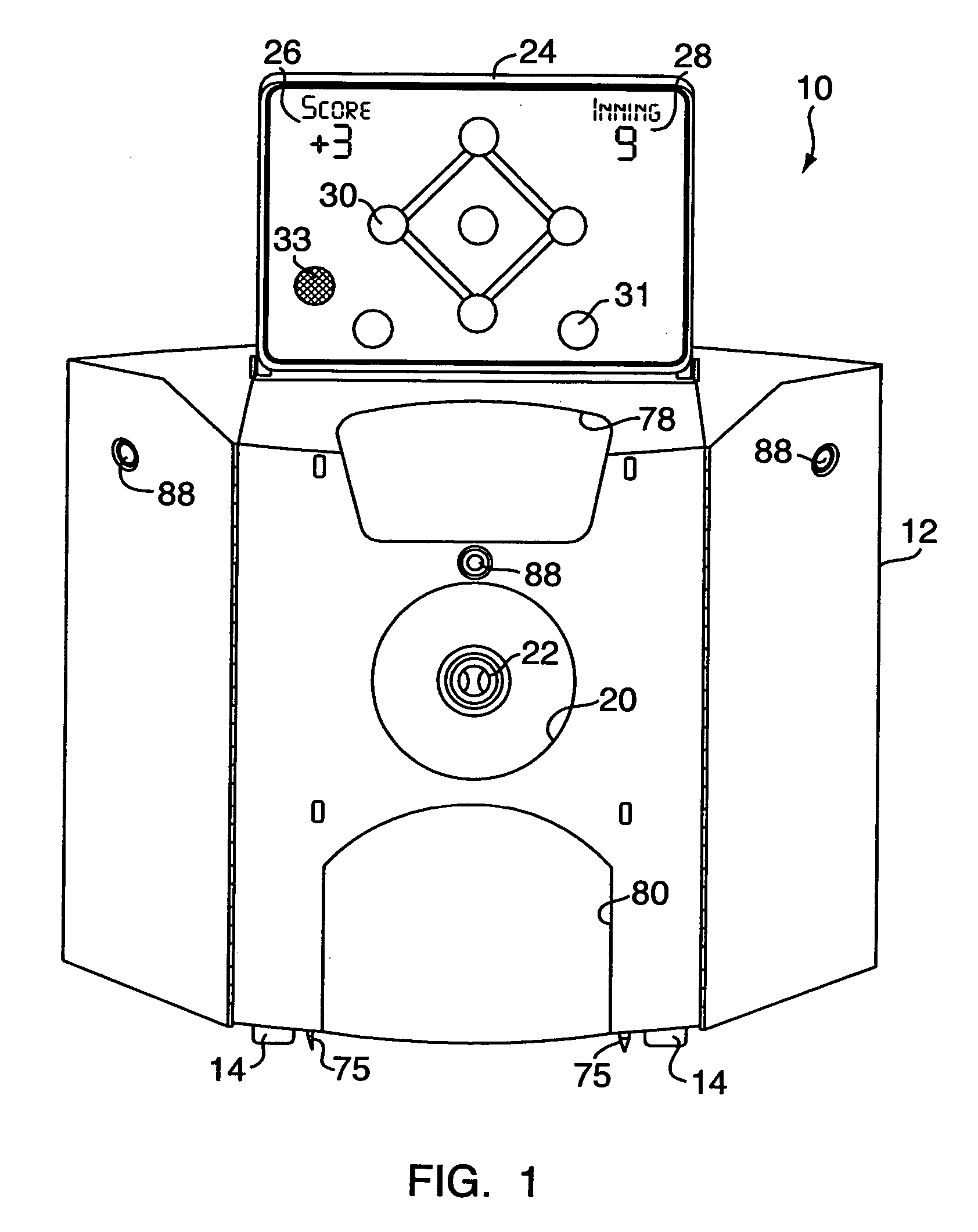
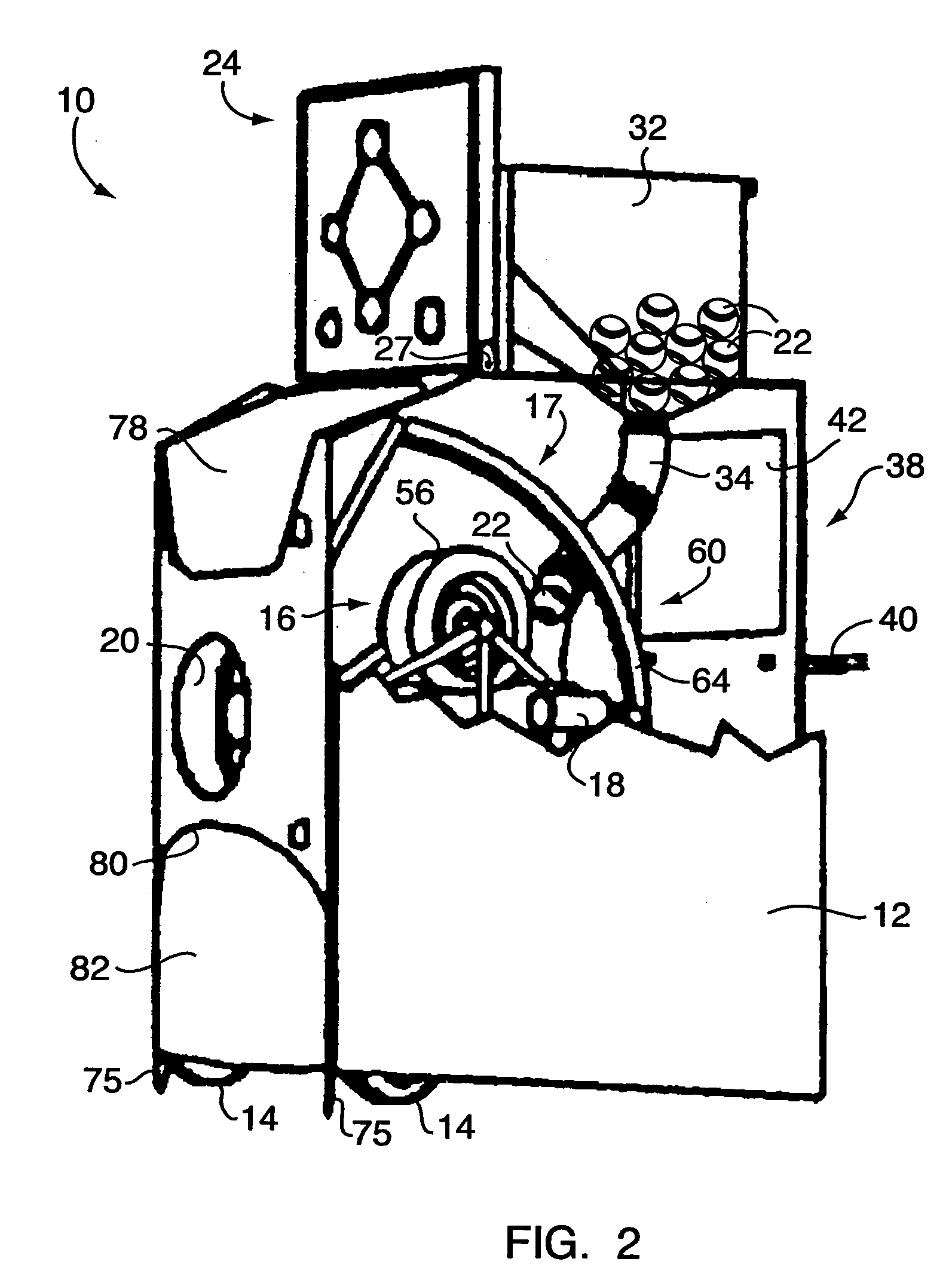
[0066]As shown in FIGS. 1–4A, the present invention is directed to a baseball fielding practice machine (referred to herein as “practice machine”) generally designated by the reference number 10. The practice machine 10 includes a housing 12 mounted on wheels 14. A propulsion unit, generally designated by the reference numeral 16, is mounted inside the housing 12. A movable barrel 18, is disposed adjacent to the propulsion unit 16. The propulsion unit 16 is for propelling balls 22 through the movable barrel 18 outwardly from the practice machine 10. The housing 12 defines a barrel opening 20 through which the balls 22 are propelled from the practice machine 10. In the illustrated embodiment, both the propulsion unit 16 and the movable barrel 18 are coupled to a barrel positioner, identified generally by the reference numeral 17. The barrel positioner 17 is controllable for moving both the propulsion unit16 and the movable barrel 18 for adjusting the trajectory of a ball 22 propelled...


PUM


Abstract

The present invention provides a baseball practice machine for propelling balls onto a practice field thereby providing simulated hits for use in fielding practice for ball players. The practice machine includes a ball hopper, a propulsion unit for propelling a ball toward a practice field, a movable barrel through which a ball is propelled. A barrel positioner is coupled to the propulsion unit and the movable barrel for adjusting the position of the barrel thereby controlling the trajectory of a propelled ball. A programmable control system controls the operation of the practice machine. Trajectory parameters for the propelled balls are selected from predetermined parameters defining the path of the ball to a location of a practice field where the ball is intended to land. Information defining the dimensions of a practice field are stored in a memory of the control system and used in determining the trajectory parameters.

Description

CROSS REFERENCE TO RELATED APPLICATIONS[0001]This application claims priority to U.S. Provisional Patent Application Nos. 60 / 465,163 filed on Apr. 23, 2003 entitled “Fielding Practice Machine” and 60 / 476,027 filed on Jun. 5, 2003 entitled “Practice Machines for Sports”. The disclosure of each of the above-identified provisional applications is incorporated herein by reference.FIELD OF THE INVENTION[0002]The present invention generally relates to a practice machine for use with baseball players, and more particularly to a baseball fielding practice machine that is positionable at a predetermined location on a practice field for propelling balls toward the practice field. The present invention practice machine provides simulated hits for use in fielding practice for baseball players.BACKGROUND OF THE INVENTION[0003]Generally, machines for projecting baseballs are well known in the art and include mostly pitching machines designed to simulate pitches for use in batting practice for bas...

Claims


Application Information

Patent Timeline
Patent Type & Authority Patents(United States)
IPC IPC(8): F41B4/00A63BA63B69/40F41B15/00
CPCA63B69/406A63B2243/0004A63B2102/18
Inventor WILMOT, THOMAS
Owner EPIC SPORTING GOODS
Why Eureka
Try Eureka