
Technoscope

Inactive Publication Date: 2006-08-01
RICHARD WOLF GMBH
View PDF19 Cites 2 Cited by
  • Summary
  • Abstract
  • Description
  • Claims
  • Application Information

AI Technical Summary

Benefits of technology

[0005]It is therefore the object of the invention to create a device which permits a simplified examination of surfaces in confined spaces or cavities.
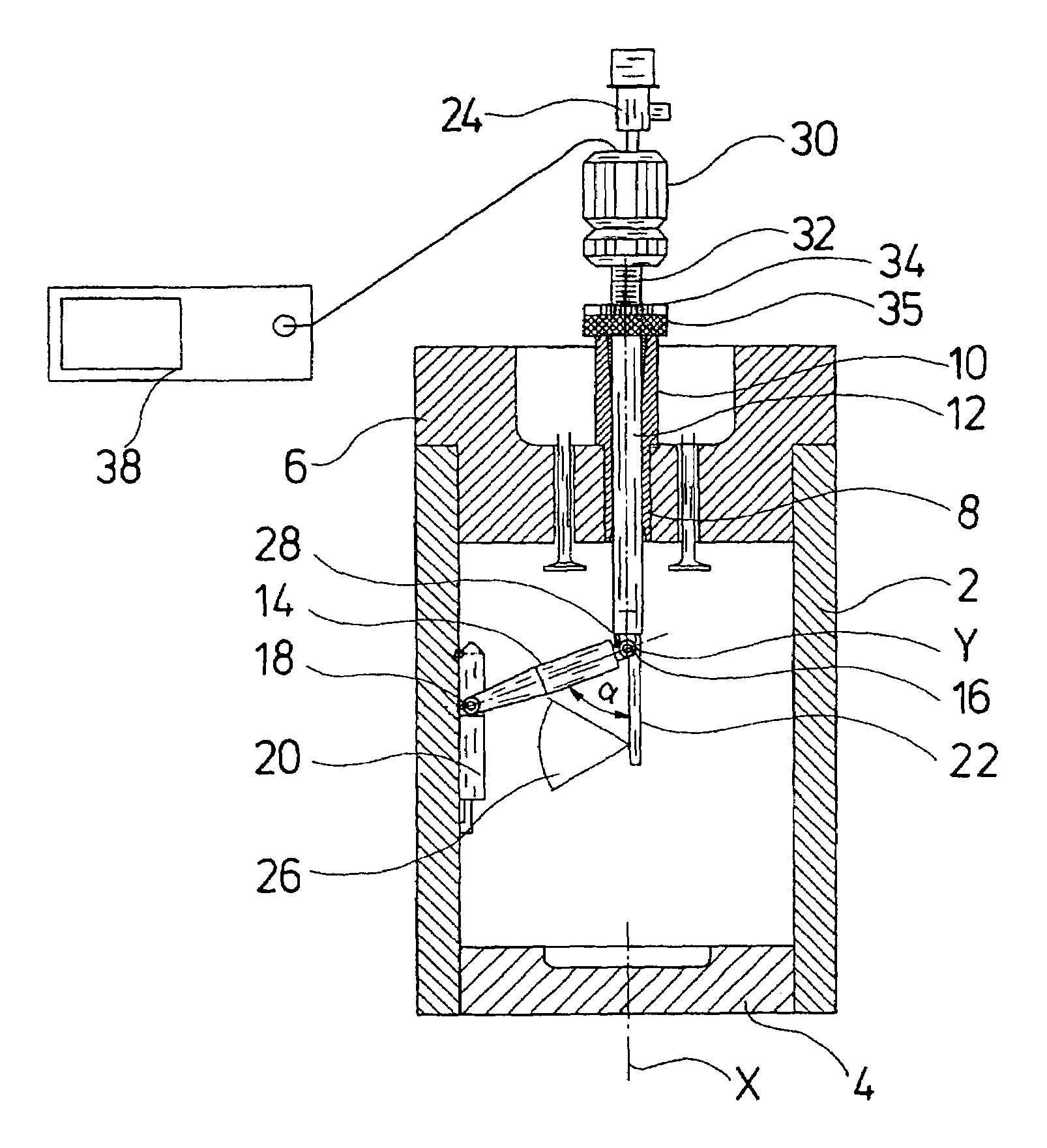
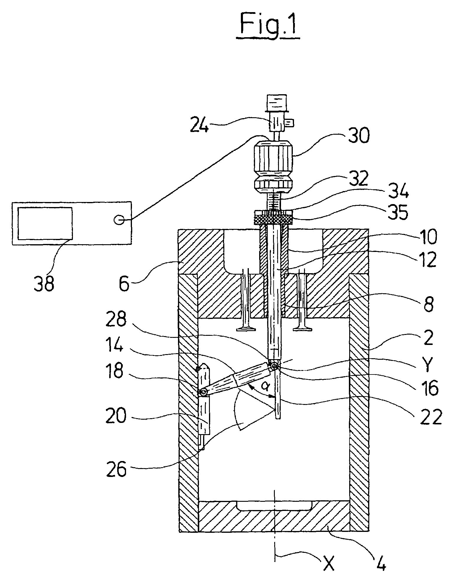
[0008]The proximal end of the arm is preferably articulated on the shank and the measuring device is attached at the distal end of the arm. This arrangement permits the maximal radial distance of the measuring device to the longitudinal axis of the shank to be achieved in order to also be able examine cavities or their inner wall with the help of the measuring device. The proximal end of the arm at the same time is articulated on in the vicinity of the longitudinal axis of the shank. The maximal radial deflection of the measuring device from the longitudinal axis of the shank is achieved at an angle of 90° between the longitudinal axis of the arm and the longitudinal axis of the shank. With this the maximal radial deflection of the measuring device is essentially dependent only on the length of the arm. This has the advantage that the technoscope may be easily adapted such that very large cavities may be examined without the diameter of the shank having to be enlarged. For larger cavities the arm merely needs to be designed correspondingly long. The shank diameter of the technoscope may be kept small so that the technoscope may be introduced into cavities through very small openings.
[0010]The measuring device is further preferably pivotably attached to the arm. This permits the measuring device to have an improved contact on the surfaces of a cavity which are to be examined. This is particularly the case if the surfaces to be examined run in an inclined or arcuate manner. The measuring device may then be pivoted relative to the arm so that it may be brought optimally into contact or into an optimal position to the surface to be examined. According to one preferred embodiment of the invention the measuring device is attached on the arm in a freely pivotable manner so that it contacts the surface to be examined in a self-adjusting manner.
[0013]The measuring device is preferably arranged pivotable relative to the arm in a manner such that a longitudinal axis of the measuring device in the first position of the arm runs parallel to the longitudinal axis of the shank and the longitudinal axis of the arm. This means that the complete technoscope in the first position of the arm is arranged extended in the longitudinal direction of the shank and has a minimal cross section which is preferably limited by the maximal cross section of the shank. The technoscope may thus be easily introduced into a narrow opening, for example a spark plug or glow plug bore or injection nozzle bore, into a cylinder space.
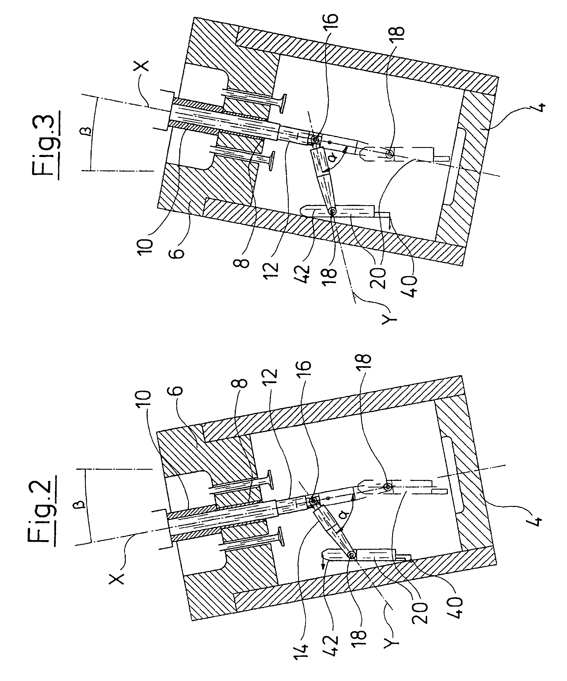
[0014]The pivot axis of the measuring device is preferably arranged between two ends of the measuring device which are opposite to one another in the longitudinal direction, and distanced to these ends. The two ends of the measuring device which are distanced to one another and to the pivot axis at the same time serve as bearing shoulders or counter bearings, which permit a simple alignment of the measuring device on the wall or surface to be examined. In particular, if the measuring device is designed such that its center of gravity is located outside its pivot axis, then with an oblique or inclined surface, one of the ends of the measuring device firstly comes into contact with the surface of the cavity to be measured on pivoting the arm. Which of the ends comes firstly into contact with the surface in particular depends on the inclination of the surface to the vertical. If the first end has come into contact with the surface, the arm is pivoted further away from the longitudinal axis of the shank, by which means the pivot axis of the measuring device may be moved more onto the surface to be examined and finally the second end of the measuring device also comes to bear on the surface. A very simple forced alignment of the measuring device parallel to the surface to be examined becomes possible in this manner.
[0020]The shank is preferably displaceably held in its longitudinal direction or held rotatable about its longitudinal axis, in the guide sleeve. This permits the shank to move in the inside of the guide sleeve with as little play as possible, in order in this manner to be able to bring the measuring device into various positions in the inside of the cavity to be examined, or with the help of the optics arranged in the shank to be able to observe various regions of the cavity. With these movements the shank is moved in the guide sleeve so that for example the radial distance of the measuring device to the longitudinal axis of the cavity to be examined may be kept constant.

Problems solved by technology

Since with motors, the service intervals are becoming less and less frequent, a simple optical inspection of the combustion space is no longer adequate.
The opening of the motor is very time-consuming and costly, in particular with large motors such as ship's motors.

Method used


Image

  • Technoscope
  • Technoscope
  • Technoscope

Examples


Embodiment Construction

[0030]FIG. 1 shows a section view of a cylinder 2 of a combustion motor, for example a ship's motor. On examination the piston 4 is preferably located at the lower dead center. A bore 8 is located in the cylinder head next to the inlet and outlet openings with the valves. The bore 8 is arranged centrally in the cylinder in the direction of the longitudinal axis X. In operation, the bore serves for accommodating the injection nozzle of the cylinder. The injection nozzle (not shown here) is screwed out for examining the inner space of the cylinder 2. A guide sleeve 10 is screwed into the bore 8 from which the injection nozzle is removed, and this sleeve has an outer thread corresponding to the inner thread in the bore 8. The shank 12 of the technoscope is inserted into the guide sleeve 10 of the technoscope from the proximal end of the guide sleeve 10. At the same time the shank 12 is introduced through the guide sleeve 10 from the outside into the inner space of the cylinder 2. An ar...


PUM


Abstract

A technoscope for examining surfaces in confined spaces includes a shank on whose distal end a pivotable arm with a measuring device is arranged, which may be pivoted from a first position in which the arm extends in the longitudinal direction of the shank into a second position in which the arm extends bent at an angle to the longitudinal axis of the shank.

Description

BACKGROUND OF THE INVENTION[0001]1. Field of the Invention[0002]The invention relates to a technoscope for examining surfaces in confined spaces or cavities.[0003]2. Description of the Related Art[0004]Technoscopes, which are known for example from U.S. Pat. No. 4,078,864, are used for the optical examination of restricted spaces, in particular difficult to access cavities of machines and motors. Such technoscopes are for example used in order to optically examine the cylinder spaces of combustion motors. Since with motors, the service intervals are becoming less and less frequent, a simple optical inspection of the combustion space is no longer adequate. The condition of the motor may be determined more exactly by way of roughness measurement of the running surfaces. For this however the motor needs to be opened in order to be able to carry out a roughness measurement on the inner walls of the cylinder. The opening of the motor is very time-consuming and costly, in particular with ...

Claims


Application Information

Patent Timeline
IPC IPC(8): G01N21/00G02B23/24
CPCG02B23/2407
Inventor DIENER, JORGSCHLAGENHAUF, FRANK
Owner RICHARD WOLF GMBH
Learn More