Externally customized tonal-hierarchy configuration and complementary business arrangements, for inkjet printing

a tonal hierarchy and business arrangement technology, applied in the direction of digital output to print units, visual presentation using printers, instruments, etc., can solve the problems of uneconomical key personnel of an extremely large manufacturer, unsuitable for major manufacturers of inkjet printers, and exacerbated problems

Active Publication Date: 2006-08-01
HEWLETT PACKARD DEV CO LP
View PDF5 Cites 7 Cited by
  • Summary
  • Abstract
  • Description
  • Claims
  • Application Information

AI Technical Summary

Benefits of technology

[0031]Central to the present invention is the idea that the processor companies are third-party vendors, not affiliates of the printer company but rather independent entities selling their RIP products directly to end-users or directly to retail outlets—separately from, but for use with, the printer. This characteristic considered alone is neither novel nor unique, but is so when considered together in conjunction with other elements of the combination described here. In addition to being novel and unique, this characteristic within the present combination is an extremely powerful and useful feature as will shortly be seen.
[0040]What this means is that the two-bit pipeline and drop table, in combination with the independent business arrangements described above, provide a remarkably potent tool for benefitting consumers while encouraging competitive, creative and constructive behavior on the part of processor companies. This benefit derives from enablement, by the data-structure conversion in the drop table, of an enormously broad range of data-interpretive capabilities.
[0041]In particular this beneficial arm's-length relationship facilitates and encourages a healthy and beneficial competition between the processor companies and the printer company. As noted above, the printer company may provide its own—or an affiliate's own—RIP which may even be internal to the printer, and this “internal RIP” may perform functions closely analogous to those of the processor companies.
[0078]In particular, the drop table enables externally controlled configuration of a customized, specialized relationship between the standardized data structure within the pipeline and an essentially arbitrary hierarchy of printable tonal-value states. Such versatility in the hierarchy of tone states is extremely valuable in accommodating unusual requirements of special-purpose print media.

Problems solved by technology

They are in fact so great in number that it is impractical for major manufacturers of inkjet printers—particularly large, printer / plotter-scale units suited for industrial use—to give adequate attention to the unique inking requirements of such diverse industrial materials.
Unfortunately for the resolution of this problem, conventional printing systems have factory-established fixed relationships between the data manipulations necessary to image rendition and the calorimetric tone hierarchies produced by actual ink on actual printing media.
On the other hand, many special printing materials are employed in relatively very specialized industries that cannot support more than a few large-format printers.
In such circumstances it becomes uneconomic for key personnel of an extremely large manufacturer to attend to such special needs on an individual basis.
This problem is exacerbated by the relative ungainliness and large overhead associated with activities of a printer manufacturing firm.
(e) Remaining limitations—Yet a partial obstacle to this solution remains.
Although in most situations an identifiable module containing the necessary mapping function is actually present in the printer, yet the problem remains because that module is relatively inaccessible to the processor company.
Furthermore its syntax may be incompletely plain to even skilled programming personnel of the processor company.
These limitations continue to impede achievement of uniformly excellent inkjet printing in greatly diverse industries.

Method used


Image

  • Externally customized tonal-hierarchy configuration and complementary business arrangements, for inkjet printing
  • Externally customized tonal-hierarchy configuration and complementary business arrangements, for inkjet printing
  • Externally customized tonal-hierarchy configuration and complementary business arrangements, for inkjet printing

Examples


Embodiment Construction

1. Apparatus-module and Business-entity Interrelations

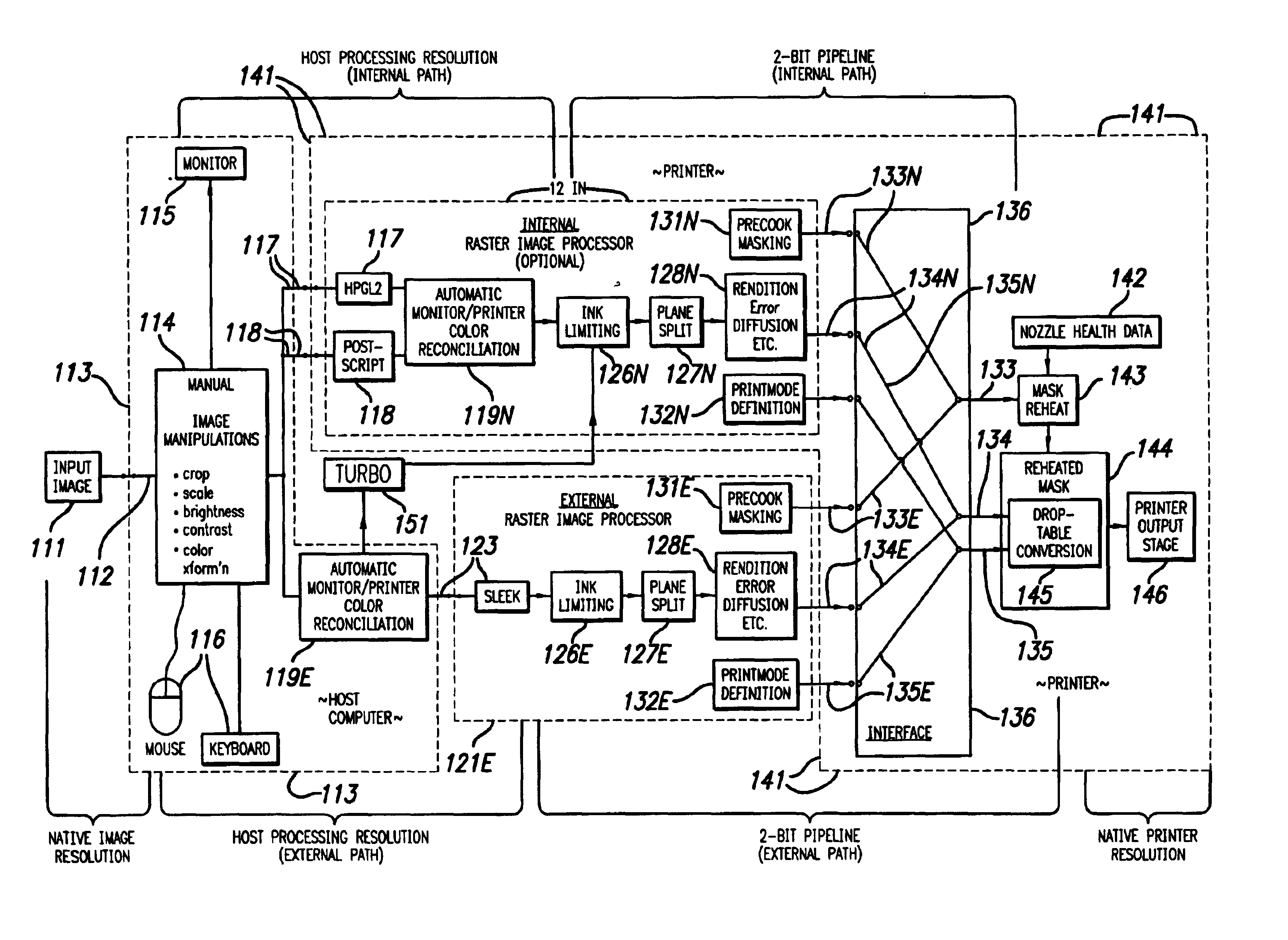
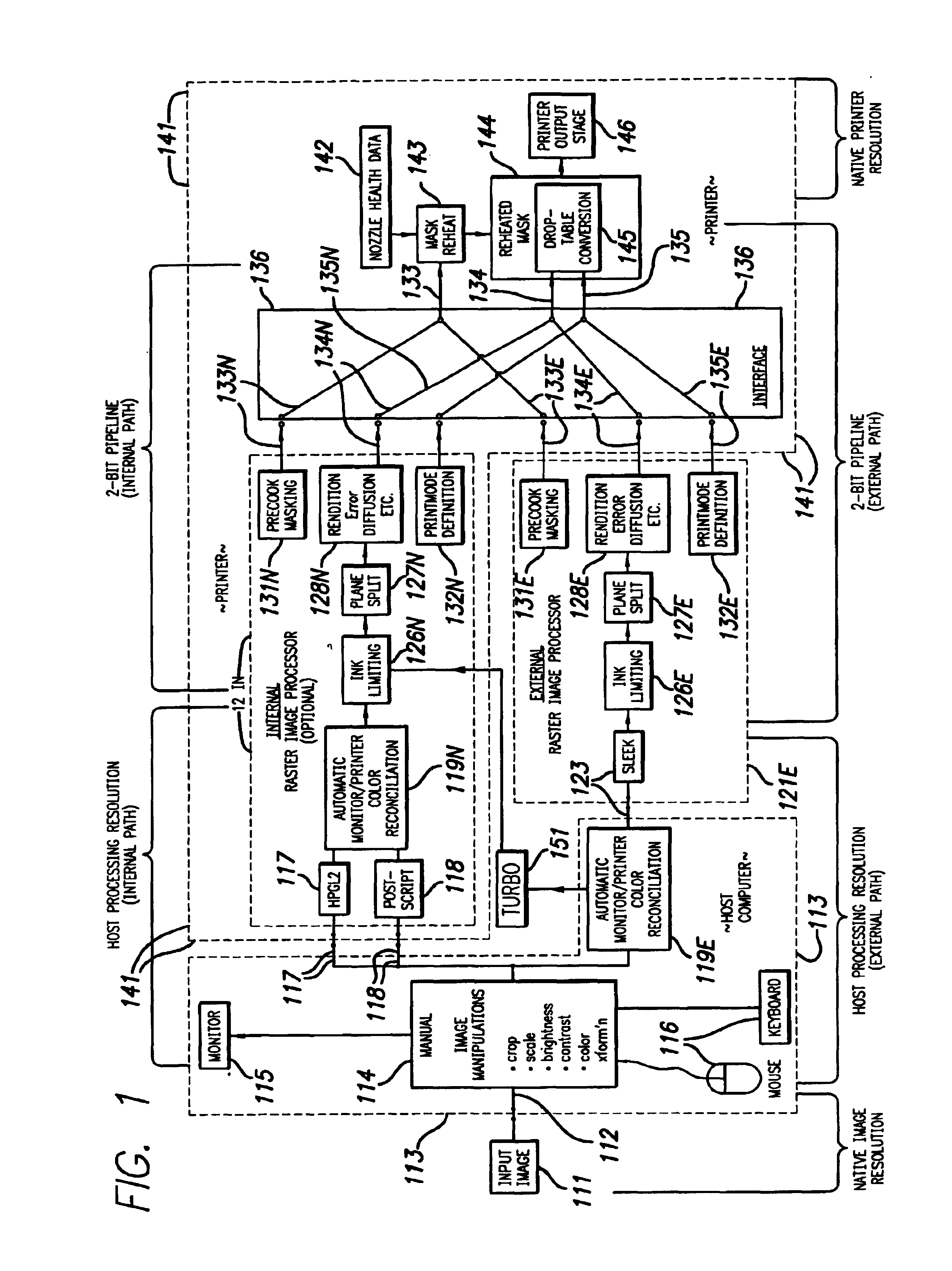
[0099]Preferred apparatus embodiments of the invention involve three major modules 113, 121E, 141 (FIG. 1), one of which can include an optional internal module 121N. Of these four units, two are parts of the environment of the invention, not elements of the invention itself as most broadly regarded: a computer 113 and an internal RIP 121N.

[0100]The remaining two units are elements of at least some of the previously introduced major apparatus aspects of the invention, again as most broadly conceived. These are the printer 141 (excluding its internal RIP 121N) and the processor or external RIP 121E. In addition, provision of one or the other of these two units 141, 121E is an element of at least one of the major method aspects of the invention.

[0101]Essential to the objectives of any such system or method is existence of an image 111, which may be derived from a separate source and then pass through an entry mechanism 112 into the...


PUM


Abstract

A printer is made by one firm; a RIP made / programmed by a separate RIP firm processes and sends to the printer image data; a two-bit data pipeline passes data through the RIP; a drop table converts data in the pipe to printer resolution. RIP firms set up the table with output dot-per-pixel structure different from the pipe. Ideally the table is in the printer but formed by the RIP; the RIP has precooked printmask instructions, and the printer, popup instructions to refine mask instructions; the instructions hide nozzle-out error and fix which pass prints each pixel; a computer, monitor etc. receive / create data and pass them to the RIP. Another aspect: a printer has a plural-bit data pipe, and interface to accept an external table to convert data from the pipe to numbers of dots per pixel. The interface best accepts a printmode recipe too.

Description

RELATED PATENT DOCUMENT[0001]A related document is another, coowned U.S. utility-patent document hereby incorporated by reference in its entirety into this document. It is in the names of Joan Manel Garcia-Reyero et al., first filed as application Ser. No. 09 / 516,007, later converted to provisional 60 / 219,315, and then made to form a basis of a nonprovisional application Ser. No. 09 / 632,197, “IMPROVEMENTS IN AUTOMATED AND SEMIAUTOMATED PRINTMASK GENERATION FOR INCREMENTAL PRINTING”, and issued as U.S. Pat. No. 6,443,556—and several earlier documents cited therein.FIELD OF THE INVENTION[0002]The invention relates generally to novel machines, operating procedures, and combinations of business procedures therewith, for incremental printing of text or graphics on printing media such as paper, transparency stock, or other glossy media, and myriad specialized surfaces ranging from virtually unabsorbent of ink to extremely absorbent; and more particularly to distributive industrial arrange...

Claims


Application Information

Patent Timeline
Patent Type & Authority Patents(United States)
IPC IPC(8): G06F3/12G06F13/00G06F5/00G06K15/02
CPCG06K15/02G06K15/1856G06K15/1848
Inventor MIGUEL, ANTONI GILGUERRERO, FRANCISCOGARCIA, JOAN MANUEL
Owner HEWLETT PACKARD DEV CO LP
Why Eureka
Try Eureka