Communications control method
- Summary
- Abstract
- Description
- Claims
- Application Information
AI Technical Summary
Benefits of technology
Problems solved by technology
Method used
Image
Examples
first embodiment
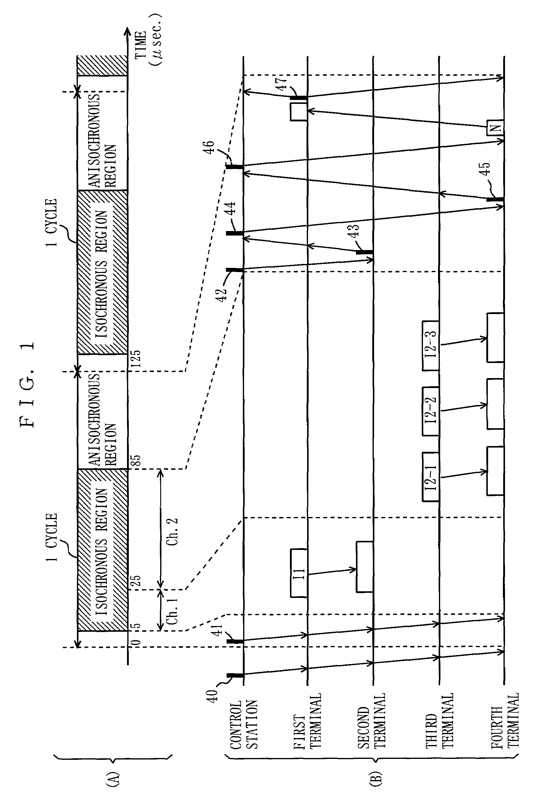
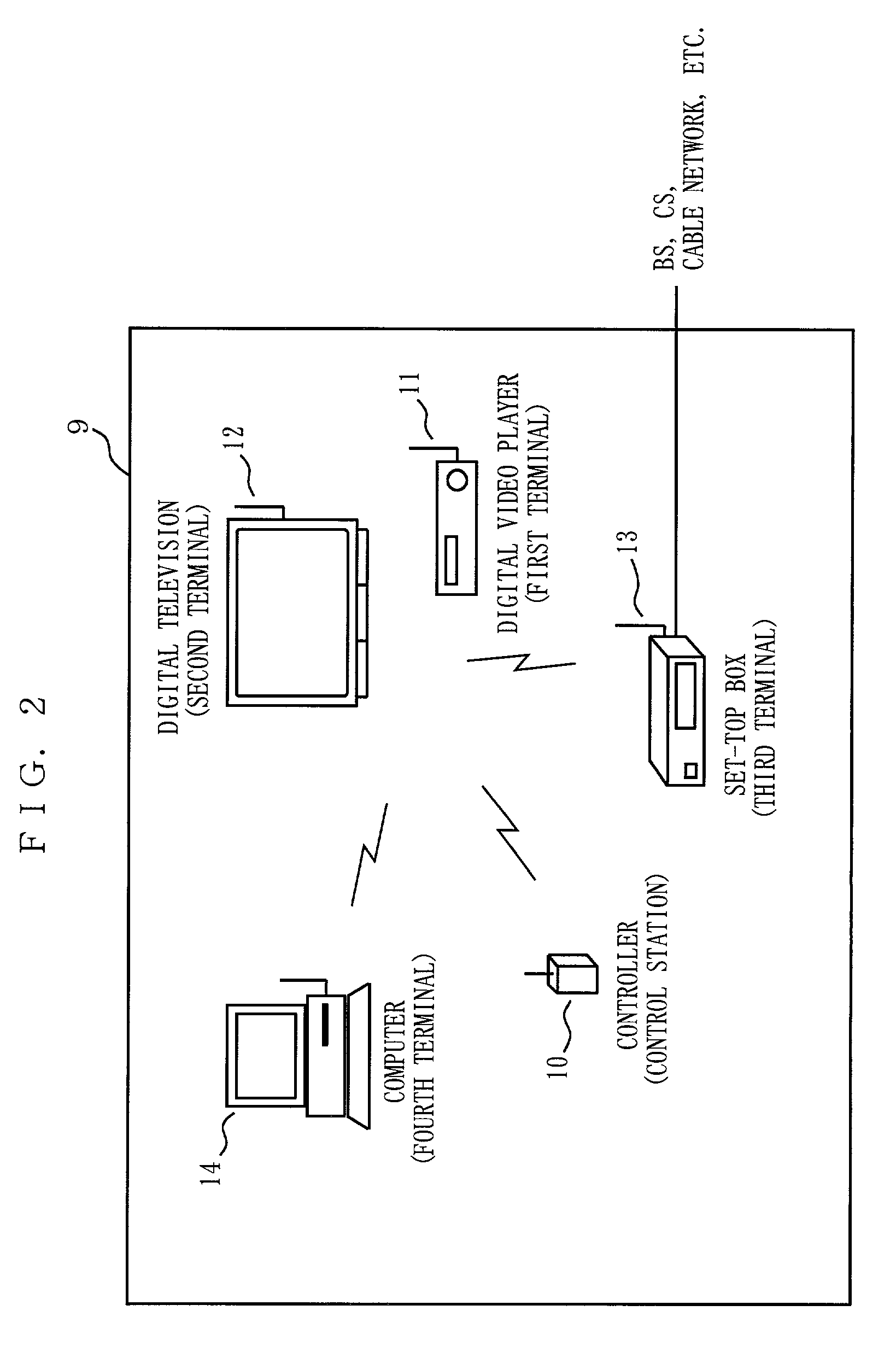
[0087]FIG. 1 is a schematic diagram for demonstrating a communications control method according to a first embodiment of the present invention. FIG. 2 is a diagram illustrating an example of the structure of a wireless local area network 9 to which the method of FIG. 1 is applied. In FIG. 2, the wireless local area network 9 includes a controller 10, a digital video player 11, a digital television 12, a set-top box (hereinafter, STB) 13, and a computer 14. These components 10 to 14 are wirelessly coupled to each other. This network 9 is almost the same as the network 209 of FIG. 23 (refer to Background Art section), except that the ratio of occurrence of transmission errors is high because of the wireless connection among the components 10 to 14. In the network 9, the controller 10 controls wireless communications among the components 11 to 14.
[0088]Each of the components 10 to 14 forming the wireless local area network 9 is provided with a wireless communications module. An example...
second embodiment
[0145]FIG. 14 is a schematic diagram for demonstrating a communications control method according to the second embodiment of the present invention. One example structure of a wireless local area network to which the method of FIG. 14 is applied is similar to that shown in FIG. 2. The structure of the wireless communications module 20 equipped in the control station and each terminal shown in FIG. 2 is similar to that shown in FIG. 3. The contents of the program memory 24 of FIG. 3 are similar to those shown in FIG. 4, except that the control station program 31 and the terminal program 32 are partly different from those according to the first embodiment.
[0146]In the example of FIG. 14, in a single isochronous region, the first terminal carries out broadcast transmission of three isochronous blocks (I1-1, I1-2, and I1-3) to the second to fourth terminals. Here, if many terminals other than those shown in the drawing exist and the second to fourth terminals belong to a single group, th...
third embodiment
[0153]FIG. 15 is a schematic diagram for demonstrating a communications control method according to the third embodiment of the present invention. An example of the structure of a wireless local area network to which the method of FIG. 15 is applied is similar to that in FIG. 2 with a fifth terminal (another computer, for example) newly added thereto. The structure of the wireless communications module 20 equipped to the control station and each terminal of FIG. 2 is similar to that shown in FIG. 3. The contents of the program memory 24 of FIG. 3 are similar to those shown in FIG. 4, except that the control terminal program 31 and the terminal program 32 are partly different from those according to the first embodiment.
[0154]FIG. 15 shows an example of retransmission control in which inquiries about whether or not reception has succeeded and retransmission instructions are made in a collective manner. In FIG. 15, in the isochronous region, multicast transmission of two isochronous b...
PUM
 Abstract
Description
Claims
Application Information
 - R&D
- Intellectual Property
- Life Sciences
- Materials
- Tech Scout
- Unparalleled Data Quality
- Higher Quality Content
- 60% Fewer Hallucinations
Browse by: Latest US Patents, China's latest patents, Technical Efficacy Thesaurus, Application Domain, Technology Topic, Popular Technical Reports.
© 2025 PatSnap. All rights reserved.Legal|Privacy policy|Modern Slavery Act Transparency Statement|Sitemap|About US| Contact US: help@patsnap.com


