Parking assist apparatus and parking assist method for vehicle

a technology for parking assist and vehicles, which is applied in the direction of braking systems, instruments, television systems, etc., can solve the problems of user inconvenience of going through the positional adjustment the accuracy limit of estimating the initial position of the target parking frame, etc., and achieve the effect of reducing the frequency of recognition of the target parking position

Active Publication Date: 2006-08-01
TOYOTA JIDOSHA KK +1
View PDF6 Cites 69 Cited by
  • Summary
  • Abstract
  • Description
  • Claims
  • Application Information

AI Technical Summary

Benefits of technology

[0022]In the fifth aspect of the invention, if a steering angle being substantially at a neutral position is detected in addition to the stopped state of the vehicle, the recognition device may recognize, as the target parking position, a position having a predetermined relationship with the stopped position of the vehicle. This arrangement reduces the frequency of recognition of a target parking position by the parking assist apparatus being triggered by the detection of a normal stopped state of the vehicle other than th...

Problems solved by technology

However, the target parking frame is not always initial-displayed in a parking position (including the orientation thereof) that is desirable to every user.
That is, there is a certain limit of the accuracy in estimating an initial position of the target parking frame because the relationship of the parking start position to a target parking position varies depending on the d...

Method used


Image

  • Parking assist apparatus and parking assist method for vehicle
  • Parking assist apparatus and parking assist method for vehicle
  • Parking assist apparatus and parking assist method for vehicle

Examples


first embodiment

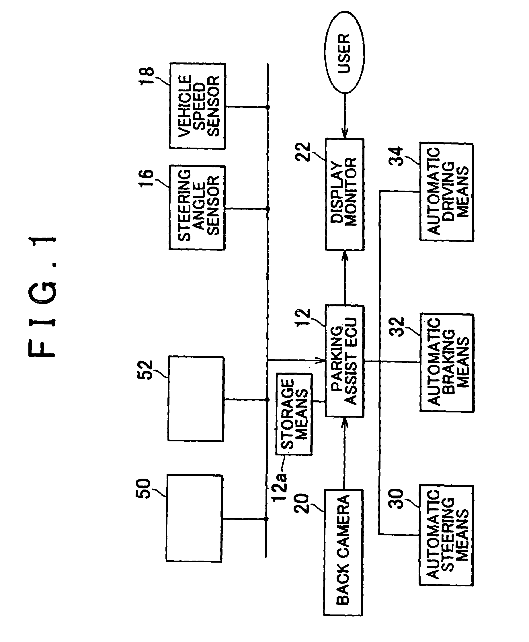
[0052]In the first embodiment, when the control parameters (Xc, Zc, θ) are determined, the parking assist ECU 12 stores the control parameters (Xc, Zc, θ) into the predetermined rewritable storage means 12a (e.g., the RAM of the parking assist ECU 12). At this time, the control parameters (Xc, Zc, θ) are stored and managed separately for garage parking and parallel parking.

[0053]Specifically, in the case of garage parking, values of the control parameters (Xc, Zc) are classified in storage in accordance with the angle θ of the vehicle to be angled to the target parking position (hereinafter, this control parameter will be referred to as “deflection angle θ”) as shown in FIG. 5. In this embodiment, ranges of the deflection angle θ are set for every 10 degrees in the positive and negative directions from 0 degree. The sign of the deflection angle θ in FIG. 5 is defined so that a leftward deflection of the vehicle as in FIG. 4B (i.e., a counterclockwise deflection from a vehicular long...

second embodiment

[0086]Next, a parking assist apparatus in accordance with the invention will be described. The parking assist apparatus of this embodiment estimates the deflection angle θ by an estimation technique as described above on the basis of the driving state of the vehicle up to the parking start position, and also estimates the aforementioned control parameters (Xc, Zc).

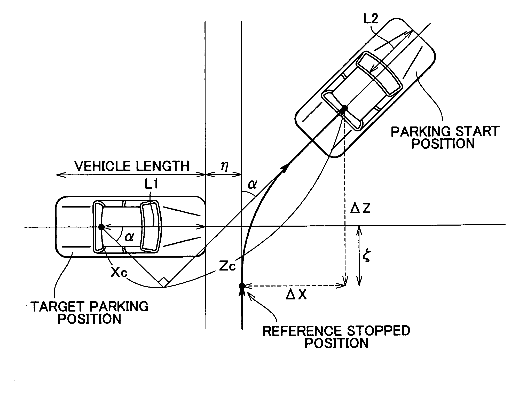
[0087]FIG. 8 is a diagram illustrating a technique for estimating the control parameters (Xc, Zc) in accordance with this embodiment. In this embodiment, the control parameter Xc (i.e., the x-coordinate of the center of the rear axle of the vehicle at the target parking position) is computed as in:

Xc=(L1+ΔX+η)•cos α−(ΔZ−ζ)•sin α  (4)

[0088]The control parameter Z (i.e., the z-coordinate of the center of the rear axle of the vehicle at the target parking position) is computed as in:

Xc=(L1+ΔX+η)•sin α+(ΔZ−ζ)•cos α  (5)

[0089]In the above-equations, L1 is the distance [m] from the center of the rear axle of the vehicle on a hor...

third embodiment

[0098]the parking assist apparatus of the invention will next be described.

[0099]This embodiment, as described in detail below, makes it possible to estimate the target parking position with high accuracy by detecting the stopped state of the vehicle and recognizing, as a target parking position, a position having a predetermined relation with the position of the vehicle occurring at the time of detection of the stopped state. Hence, it becomes possible to initial-display the target parking frame in a desired target parking position from the beginning.

[0100]FIG. 9 is a diagram illustrating a target parking position estimating method for garage parking in accordance with the embodiment. In the target parking position estimating method of this embodiment, a precondition is that, as indicated in FIG. 9, the vehicle approaches a target parking position perpendicularly thereto, and temporarily stops at a center of the target parking position (a center line of the target parking position ...


PUM


Abstract

A parking assist apparatus allows a target parking position to be set by a user moving a target parking frame displayed together with an actual image of surroundings of a vehicle, and automatically guides the vehicle to the set target parking position. In the parking assist apparatus, the target parking frame is initially displayed through the use of past setting of the target parking position by the user.

Description

INCORPORATION BY REFERENCE[0001]The disclosures of Japanese Patent Applications No. 2003-108323 filed on Apr. 11, 2003 and No. 2003-144607 filed on May 22, 2003, including the specifications, drawings and abstracts thereof, are incorporated herein by reference in their entireties.BACKGROUND OF THE INVENTION[0002]1. Field of the Invention[0003]The invention relates to a parking assist apparatus and a parking assist method for performing a parking assist control of automatically guiding a vehicle to a target parking position.[0004]2. Description of the Related Art[0005]In a known parking assist apparatus as described in Japanese Patent Application Laid-Open Publication No. 11-208420 which performs a parking assist control of automatically guiding a vehicle to a target parking position, a target parking frame is displayed in a superimposed fashion on an actual image of surroundings of the vehicle displayed on a display monitor before the parking assist control starts. In this parking a...

Claims


Application Information

Patent Timeline
IPC IPC(8): G06F7/00B60S9/00B60Q1/48B62D15/02
CPCB60Q1/48B62D15/0285B60T2201/10
Inventor ENDO, TOMOHIKOSATONAKA, HISASHIKUBOTA, YUICHIMATSUI, AKIRAIWAKIRI, HIDEYUKISUGIYAMA, TORUKAWAKAMI, SEIJIIWAZAKI, KATSUHIKOKATAOKA, HIROAKITANAKA, YUUIWATA, YOSHIFUMI
Owner TOYOTA JIDOSHA KK
Why Eureka
Try Eureka