Pallet assembly

a pallet and assembly technology, applied in the field of pallet assembly, can solve the problems of warping of wood, difficult cleaning of wood, and relatively heavy wood pallets, and achieve the effect of uniform dimensioning, low manufacturing cost and convenient assembly

Inactive Publication Date: 2006-08-08
REHRIG PACIFIC CO INC
View PDF10 Cites 11 Cited by
  • Summary
  • Abstract
  • Description
  • Claims
  • Application Information

AI Technical Summary

Benefits of technology

[0010]It is a principal object according to the present invention to provide an improved pallet assembly which is relatively lightweight, inexpensive to manufacture and assemble, and consistently dimensioned.
[0011]It is another object according to the present invention to provide an improved pallet assembly which has desirable strength, stiffness, creep, and deflection properties.
[0012]It is another object according to the present invention to provide an improved pallet assembly which is able to withstand varied environmental conditions, particularly moisture, with little damage or wear and is readily reusable.

Problems solved by technology

First, wood pallets are relatively heavy.
Second, wood is not easily cleaned because it absorbs water and other liquids which damage and warp the wood.
For these same reasons, the use of wood pallets outside or in wet environments is also limited.
Wood pallets are often not consistently dimensioned due to size variations in the wood slats and shrinkage of wood over time, thus preventing such pallets from being stacked or stored in a stable or consistent manner.
Also, inconsistent dimensions make automation of these pallets more difficult.
Further, the nails used to fasten wood pallets together may cause damage to goods which are stored and transported on the pallet, or wood splinter may result after time.
Moreover, once wood pallets are damaged, they have little or no residual value and also necessitate disposal fees.
While many plastic pallets have been attempted, the designs that are able to approximate the strength of wood, to date, have been cost prohibitive and may not have the requisite strength properties.
While conventional plastic pallets have ribbed supports to decrease their weight, they often lack the desired stiffness and low creep properties of the solid pallet, and in order to improve these properties, the height of the pallet must be increased, or reinforcements must be added to the plastic such as steel or other composite reinforcements.
Of course, these additions to the plastic cause an increase in material density leading to an even heavier pallet.
Further, engineering resins are very expensive resulting in a more expensive pallet.
Another hurdle to overcome with plastic is the cost.
Another major hurdle is the stiffness of plastic pallets.
Racking loaded pallets in warehouses for upwards of 30 days may be common, and the combination of low tensile strength and creep may limit the use of plastic in this manner.
This generally adds significant cost and weight and complicates recycling of the pallet.
This generally limits the height of a product which is to be stacked on the pallet, as well as the number of pallets that may be stored in a given area.
Again, this adds significant cost and weight.
All three obviously limit the acceptance of plastic pallets.
However, this solution does not resolve the bending stiffness problem because large lateral and longitudinal unsupported areas still exist, such as in areas 26, 37, 38, 49 and 50.
Such a high modulus material is apparently required because the structure described does not provide significant resistance to deflection along the length and width of the pallet.
High modulus materials add substantial cost to the pallet.
Moreover, pallets typically require large openings for receipt of pallet jacks.
Because of these large openings, the pallet structure is typically thin and weak and has poor deflection stiffness.

Method used


Image

  • Pallet assembly
  • Pallet assembly
  • Pallet assembly

Examples


Embodiment Construction

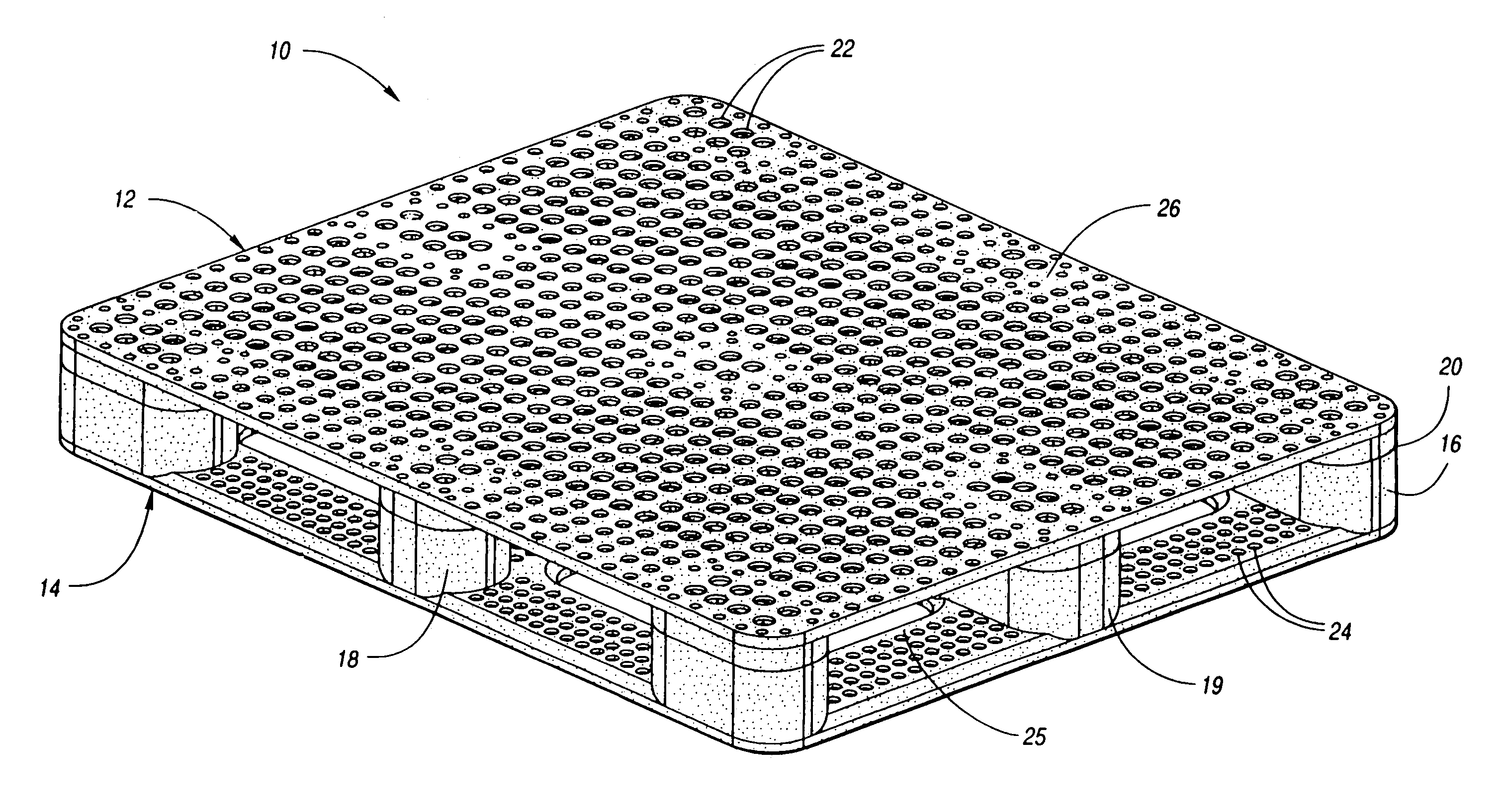
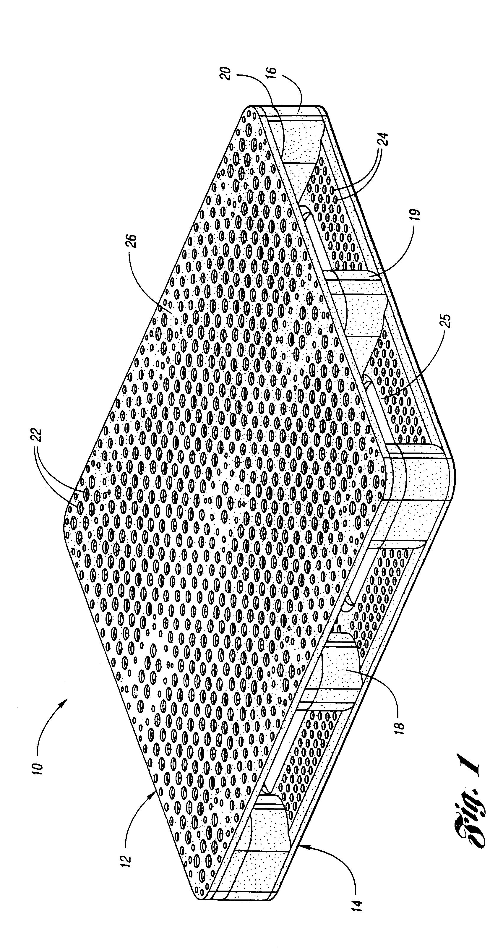
[0070]FIG. 1 of the drawings shows a top perspective view of a pallet assembly 10 according to the present invention. Pallet assembly 10 is formed of a thermoplastic or other polymeric material and is preferably, but not necessarily, formed of injection molded components. As illustrated in FIG. 1, pallet assembly 10 includes a top deck 12 and a bottom deck 14 which are spaced apart from each other. Pallet assembly 10 also includes a plurality of columns which extend between the spaced apart top deck 12 and bottom deck 14. The pluralities of columns include corner column portions 16, side column portions 18, and end column portions 19 shown extending between top deck 12 and bottom deck 14. The columns are shown having smooth, rounded outer surfaces in order to prevent damage from fork lift trucks and the like. However, any suitable contour may be used depending on the application. In addition to separating top deck 12 and bottom deck 14, column portions 16, 18, 19 and 32 serve to bea...


PUM

PropertyMeasurementUnit
wavelengthsaaaaaaaaaa
sizeaaaaaaaaaa
shrinkageaaaaaaaaaa

Abstract

A pallet includes a first component which has a first upper surface, and a first lower surface which includes a first plurality of cross-rib members. A second component has a second lower surface, and a second upper surface which includes a second plurality of cross-rib members corresponding and mounted to the first plurality of cross-rib members. A third component is adjacent the second component and has a third upper surface, and a third lower surface which includes a third plurality of cross-rib members. A fourth component has a fourth upper surface which includes a fourth plurality of cross-rib members corresponding and mounted to the third plurality of cross-rib members. A plurality of intermediate column members extend between the second lower surface and third upper surface.

Description

CROSS-REFERENCE TO RELATED APPLICATION[0001]This application is a continuation Ser. No. 09 / 944,480 filed Sep. 1, 2001, now U.S. Pat. No. 6,644,219 which is a continuation of U.S. utility application Ser. No. 09 / 330,150 filed Jun. 11, 1999 now U.S. Pat. No. 6,283,044, which is a continuation-in-part of U.S. utility application Ser. No. 09 / 108,532 filed Jul. 1, 1998, now U.S. Pat. No. 6,250,234.TECHNICAL FIELD[0002]This invention relates to a plastic pallet assembly for storing or transporting goods.BACKGROUND ART[0003]Pallets used in industry today are most commonly formed of wood slats and stringers or blocks which are nailed together. While such pallets are functional, they have many disadvantages. First, wood pallets are relatively heavy. Second, wood is not easily cleaned because it absorbs water and other liquids which damage and warp the wood. For these same reasons, the use of wood pallets outside or in wet environments is also limited. Wood pallets are often not consistently ...

Claims


Application Information

Patent Timeline
Patent Type & Authority Patents(United States)
IPC IPC(8): B65D19/00B29C65/02B29C65/14B29C65/20B29C65/78
CPCB29C65/02B29C66/54B29C66/92655B65D19/0012B65D19/0022B29C65/2061B29C65/20B29C66/543B29C66/92653B29C65/1412B29C65/78B29L2031/7178B65D2519/00034B65D2519/00069B65D2519/00104B65D2519/00273B65D2519/00293B65D2519/00303B65D2519/00308B65D2519/00323B65D2519/00333B65D2519/00358B65D2519/00363B65D2519/00432B65D2519/00557B65D2519/00562B65D2519/00567B65D2571/00055B65D2519/00412B65D2519/00407B29C66/53462B29C65/14B29C66/83221B29C66/1122B29C66/1142B29C66/1312B65D19/00
Inventor APPS, WILLIAM P.
Owner REHRIG PACIFIC CO INC
Why Eureka
Try Eureka