Rock boring device with an oscillating and nutating rotary disc cutter

a technology of rotary disc cutter and boring device, which is applied in the direction of cutting machines, mining structures, earthwork drilling and mining, etc., can solve the problem of reducing the supporting structure mass of the proposed technology, and achieve the effect of reducing the supporting structure mass

Inactive Publication Date: 2007-02-27
ODYSSEY TECH
View PDF39 Cites 78 Cited by
  • Summary
  • Abstract
  • Description
  • Claims
  • Application Information

AI Technical Summary

Benefits of technology

[0005]It is an object of the following invention to overcome, or at least reduce one or more of the disadvantages associated with prior art boring devices. It is a further object of the invention to provide a mechanical device of a rotary cutting type, that provides improved rock removal from a rock face to form a rock bore and which is relatively economical to manufacture and operate. The cross section of this bore may be circular, or a polygon, or a planar surface. (Longwall in Coal or a quarry floor).
[0008]The boring device is characterised in that the disc cutter is driven in an oscillating manner, and also driven to nutate or free to nutate. The disc cutter is driven to move in this manner about separate or combined oscillating and nutating axes. The nutation angle may be varied or fixed from 0° to almost 90° (Most probably less than 5°). That motion, when applied to the rock face, will cause the disc cutter to apply force to the rock that promotes cracks which propagate toward the rock face adjacent the opening. By this mechanism rock fragments or chips can be separated from the rock when a crack propagates from the wall of the opening to the adjacent rock face. The crack will propagate from a pressure bulb created by the motion of the oscillation, nutation or combination of both motions. This cutting action enables the rock to fail in tension rather than the current traditional compressive first then tension technique. This phenomenon significantly reduces the supporting structure mass for the proposed technology. To insure that the cutting mechanism does not move away from the rock being cut, rather than cut the rock, a mass surrounding the cutter may be necessary.

Problems solved by technology

That motion, when applied to the rock face, will cause the disc cutter to apply force to the rock that promotes cracks which propagate toward the rock face adjacent the opening.
This phenomenon significantly reduces the supporting structure mass for the proposed technology.

Method used


Image

  • Rock boring device with an oscillating and nutating rotary disc cutter
  • Rock boring device with an oscillating and nutating rotary disc cutter
  • Rock boring device with an oscillating and nutating rotary disc cutter

Examples


Embodiment Construction

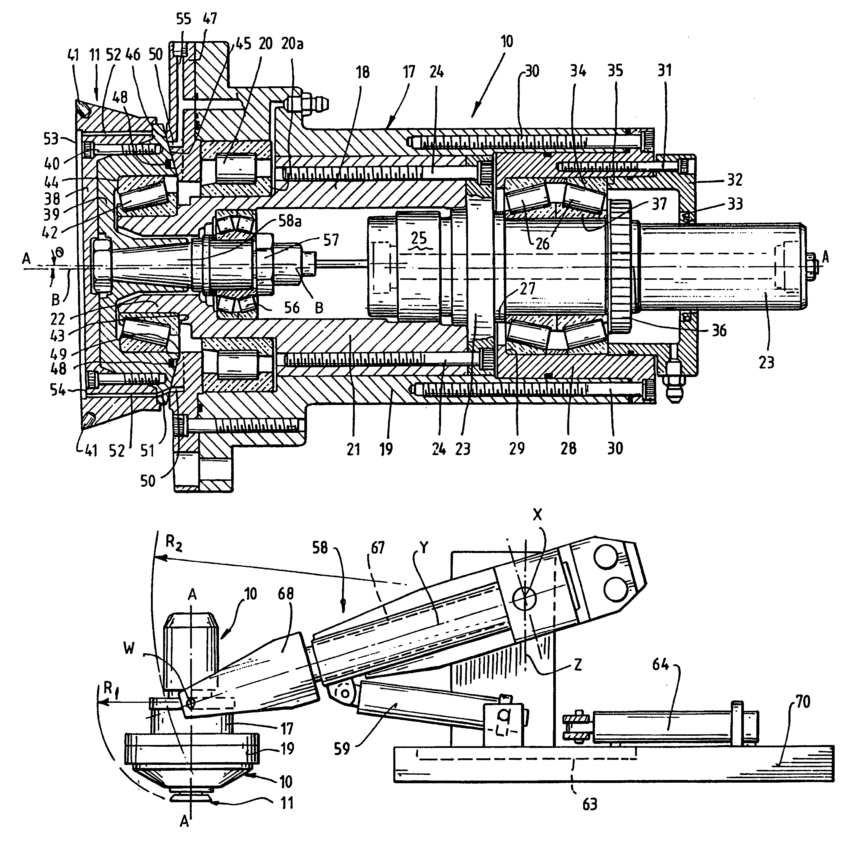
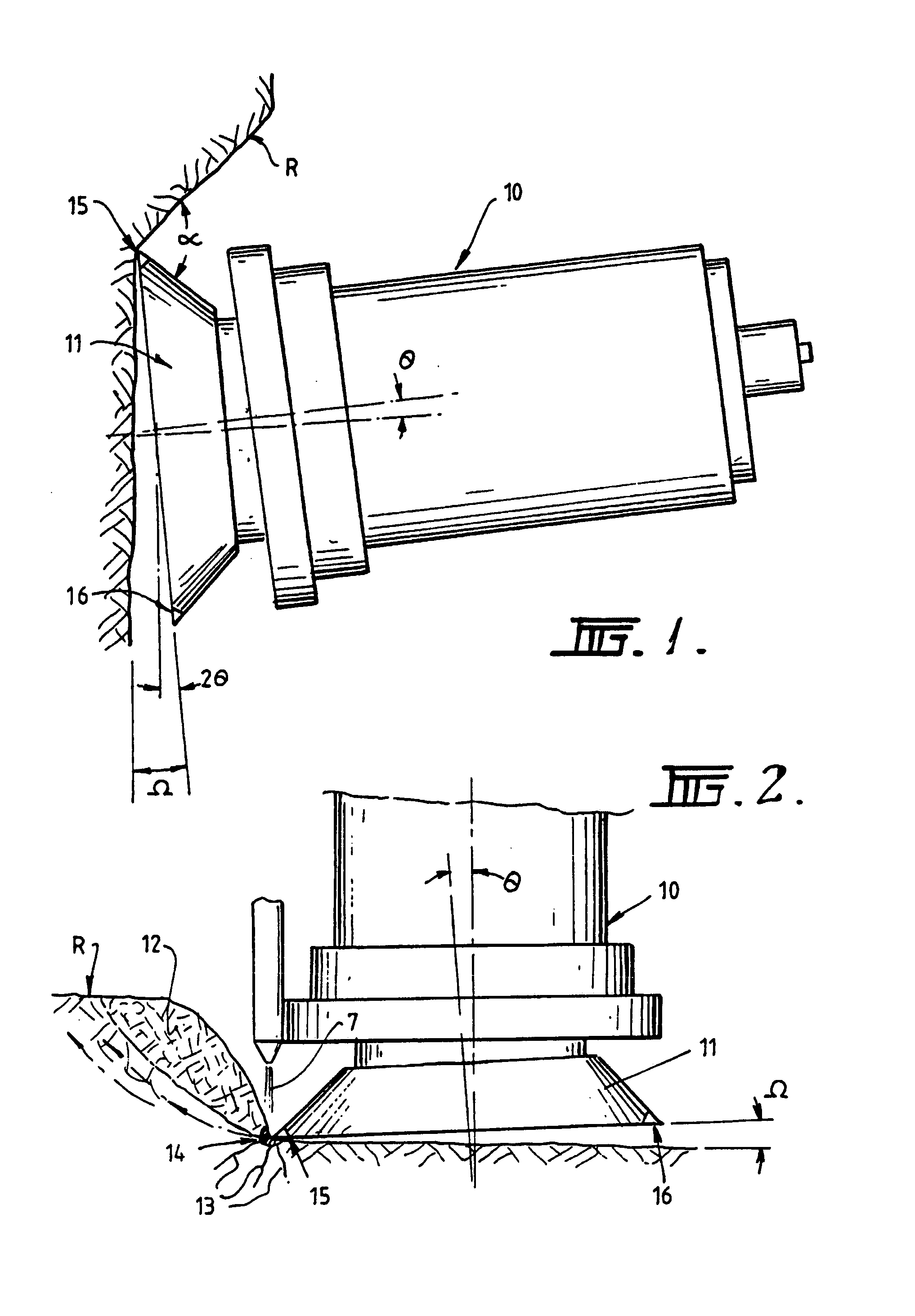
[0016]With reference to FIGS. 1 and 2 of the drawings, the rock boring device 10 according to this preferred embodiment of the present invention includes a rotary disc cutter 11, that in use, is either inserted into a pilot opening formed in the rock face R, or approaches the rock face at an angle (α) to enable entry (see FIG. 1).

[0017]For this cutting action to be initiated the tip of the disc should initially contact the rock at significant angle. (Probably in excess of 45°, [α] but differing rock types or conditions may reduce or increase this requirement).

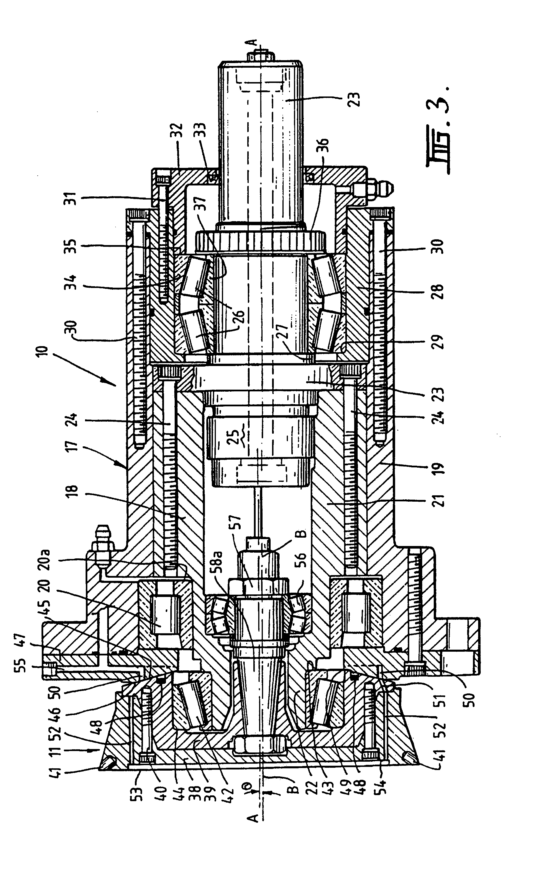
[0018]The boring device 10 is characterised in that the disc cutter 11 is driven in an oscillating manner, and also driven to nutate or is free to nutate. The disc cutter 11 is driven to move in this manner about separate or combined oscillating and nutating axes. The nutation angle (θ) may be varied or fixed from 0° to almost 90° (Most probably less than 5°). That motion, when applied to the rock face, will cause the disc cutt...


PUM


Abstract

A rock boring device (10) including a rotary disc cutter (11). The disc cutter (11) is driven in an oscillating manner and also driven or free to nutate, and the device includes a mounting section (22) for the rotary disc cutter and a driven section (21), and wherein the mounting section (22) is angularly offset from the axis of the driven section whereby the rotary disc cutter will both oscillate and nutate.

Description

CROSS-REFERENCE TO PRIORITY APPLICATION[0001]This is a national phase application of PCT / AU00 / 00030, filed Jan. 20, 2000, pending, which claims the benefit of Australian Patent Application, No. PP 8224, filed Jan. 20, 1999, each incorporated herein by reference in its entirety.TECHNICAL FIELD[0002]The present invention relates to a boring device for creating bore holes in rock, or removing rock from a surface. (For example the floor of a quarry).BACKGROUND ART[0003]Boring of holes in rock faces can be conducted in a variety of ways. For example, explosive boring, as the name suggests, involves drilling in the rock face a central primary hole and a series of secondary holes about the primary hole. The secondary holes have a diameter suitable to receive an explosive charge, while the primary holes provides an opening in the rock towards which cracks that are formed in the rock after detonation of the explosive, can propagate. The primary hole is normally of a greater diameter than the...

Claims


Application Information

Patent Timeline
Patent Type & Authority Patents(United States)
IPC IPC(8): E21C25/16E21D9/10
CPCE21C25/16E21D9/1046E21D9/1013
Inventor PEACH, ANTHONY JOHNJONES, ALWYN ARTHURJURASOVIC, ANTON JOSEPJOHNSTONE, GEOFFREY PETERCUSICK, WAYNE ANTHONYSUGDEN, DAVID BURNETT
Owner ODYSSEY TECH
Why Eureka
Try Eureka