Multi-function surgical instrument for facilitating ophthalmic laser surgery

a multi-functional, laser surgery technology, applied in the field of ophthalmic surgery, can solve the problems of affecting the size of the tissues, affecting the function of the surgical instrument, and affecting the quality of the surgical procedure,

Inactive Publication Date: 2006-08-08
LAHAYE LEON C
View PDF3 Cites 12 Cited by
  • Summary
  • Abstract
  • Description
  • Claims
  • Application Information

AI Technical Summary

Problems solved by technology

At present there is no multi-function tool specifically designed with each of these objectives in mind, rather individual ophthalmic surgeons are left to improvise their own technique for accomplishing these objectives, using a plurality of instruments that a particular surgeon may select from any number of tools that were developed for other tasks, sometimes with less than desirable results.
As hydration of the tissues being ablated alters not only the effect of the laser on that tissue (which can result in inadequate dosage, over dosage or uneven dosage) but it also alters the size of these tissues (for instance, making refit of over-hydrated tissues temporarily removed without wrinkling, difficult or impossible); controlling hydration of both the surgical bed and temporarily removed tissues is important.
It is also important to control smoke, plume and splatter not only because they may result in uneven distribution of treatment, but for other reasons relating to the health of both the patient and the surgical staff and, of course, preventing contamination, cleansing, and disinfection of open tissues is always an issue.
Moreover LASIK brings with it a unique set of issues.

Method used


Image

  • Multi-function surgical instrument for facilitating ophthalmic laser surgery
  • Multi-function surgical instrument for facilitating ophthalmic laser surgery
  • Multi-function surgical instrument for facilitating ophthalmic laser surgery

Examples


Embodiment Construction

[0016]While the present invention will be described with reference to preferred embodiments, it will be understood by those skilled in the art that various changes may be made and equivalents may be substituted for elements thereof without departing from the scope of the invention. In addition, modifications may be made to adapt a particular situation or material to the teachings of the invention without departing from the essential scope thereof. It is therefore intended that the present invention not be limited to the particular embodiments disclosed herein, but that the invention will include all embodiments (and legal equivalents thereof) falling within the scope of the appended claims.

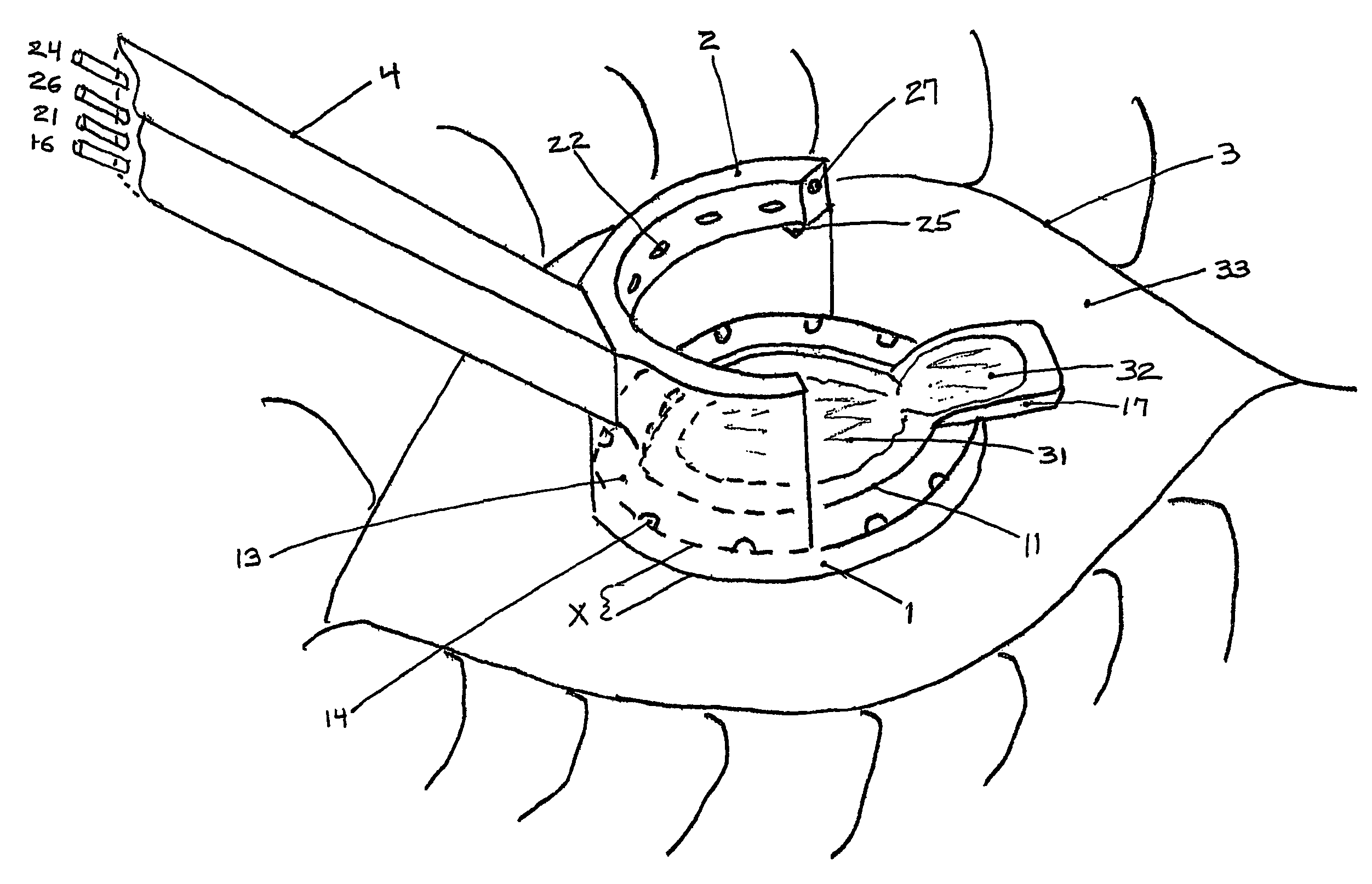
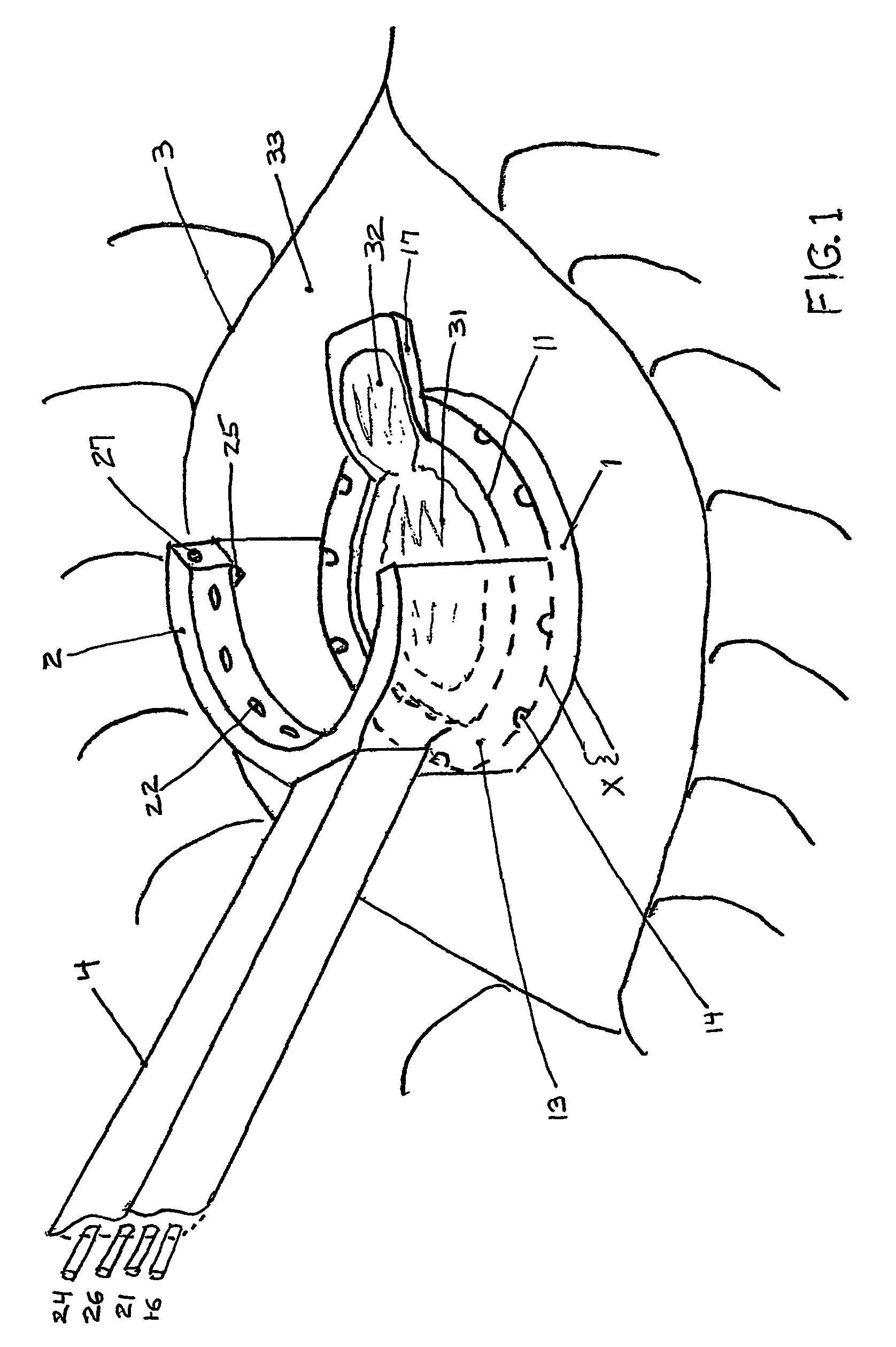
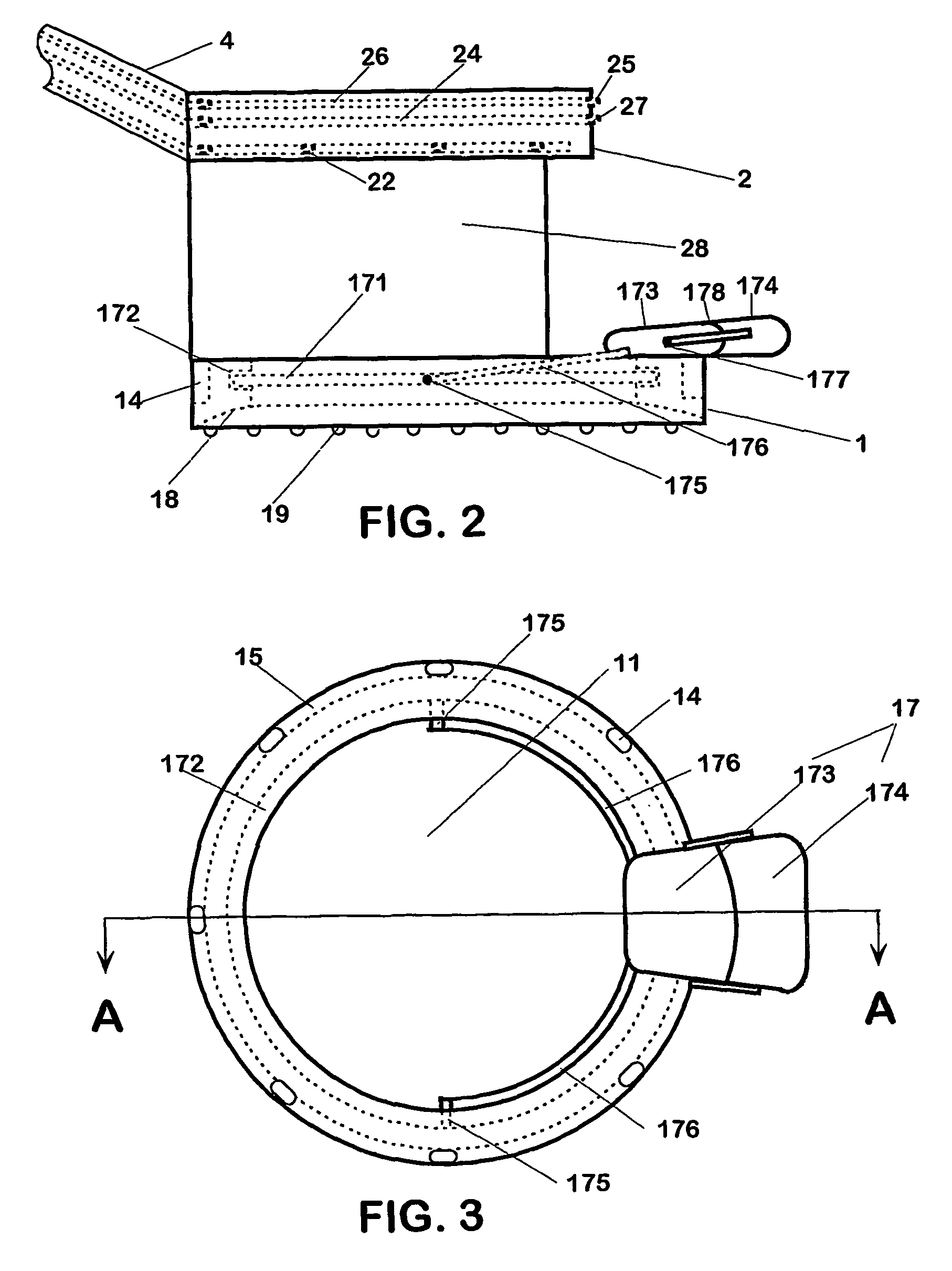
[0017]Positioning and Fixation of the Eye:

[0018]Positioning and fixation of the eye is accomplished through use of lower ring 1, in combination means for the ophthalmic surgeon to control position of the lower ring 1 itself. In the preferred embodiment lower ring 1 will be constructed of a rigid, ...


PUM


Abstract

A multi-function surgical instrument for facilitating ophthalmic surgery of the eye (3) by laser means, included are a lower ring (1) and an upper ring (2). One or two intermediate rings may also be included. The lower ring (1) includes a central aperture (11) to capture the limbus and aid in positioning of the eye (3). Protuberances on the lower surface (18) of said ring (1), application of vacuum between the lower surface (18) of the ring (1) and the eye (3), or both may be used to more firmly grip the eye (3). Ports (14) disposed on the upper surface (13) of the lower ring (1) and connected to a vacuum source may be used to control hydration of the surgical field. Attached to structures of the lower ring (1) is a sterile platform (17) for reposing temporarily removed tissues (32) during the administration of laser pulses to other tissues. The upper ring (2) is disposed above the surgical bed. Ports (22) disposed along said upper ring (2) and connected to a vacuum source may be used to control smoke and splatters resulting from the ablative procedure and create additional airflow to further control hydration of the surgical field.

Description

[0001]This patent application is a continuation-in-part application of U.S. patent application Ser. No. 10 / 071,430 filed Feb. 8, 2002, now U.S. Pat. No. 6,656,197, which is a continuation-in-part application of U.S. patent application Ser. No. 09 / 960,582 filed Sep. 21, 2001, now U.S. Pat. No. 6,569,153, which is a continuation-in-part application of U.S. patent application Ser. No. 09 / 894,264 filed Jun. 28, 2001, all of which are presently pending.[0002]1. Field of the Invention[0003]In the field of ophthalmic surgery the use of lasers is well known. In laser assisted in-situ kerotomileusis outer tissues of the cornea are temporarily removed and pulses of laser used to remove selected portions of underlying tissue re-contouring it as desired, so that after replacement, the thickness and curvature of the cornea will have desirable changes (resulting in a desired refractory result). During such procedure, and other ophthalmic procedures involving ablation of eye tissue, the ophthalmic...

Claims


Application Information

Patent Timeline
Patent Type & Authority Patents(United States)
IPC IPC(8): A61B18/18A61F9/00A61F9/009A61F9/01A61F9/013
CPCA61F9/013A61F9/009A61F9/008A61F2009/00872
Inventor LAHAYE, LEON C.
Owner LAHAYE LEON C
Why Eureka
Try Eureka