Reflection type compound prism and optical pickup apparatus employing the same

Inactive Publication Date: 2006-08-08
SAMSUNG ELECTRONICS CO LTD
View PDF24 Cites 31 Cited by
  • Summary
  • Abstract
  • Description
  • Claims
  • Application Information

AI Technical Summary

Benefits of technology

[0009]To solve the above-described problems, it is an object of the present invention to provide a reflection type

Problems solved by technology

Thus, it is difficult to manufacture a

Method used


Image

  • Reflection type compound prism and optical pickup apparatus employing the same
  • Reflection type compound prism and optical pickup apparatus employing the same
  • Reflection type compound prism and optical pickup apparatus employing the same

Examples


Example

[0032]Reference will now be made in detail to the present embodiments of the present invention, examples of which are illustrated in the accompanying drawings, wherein like reference numerals refer to like elements throughout.

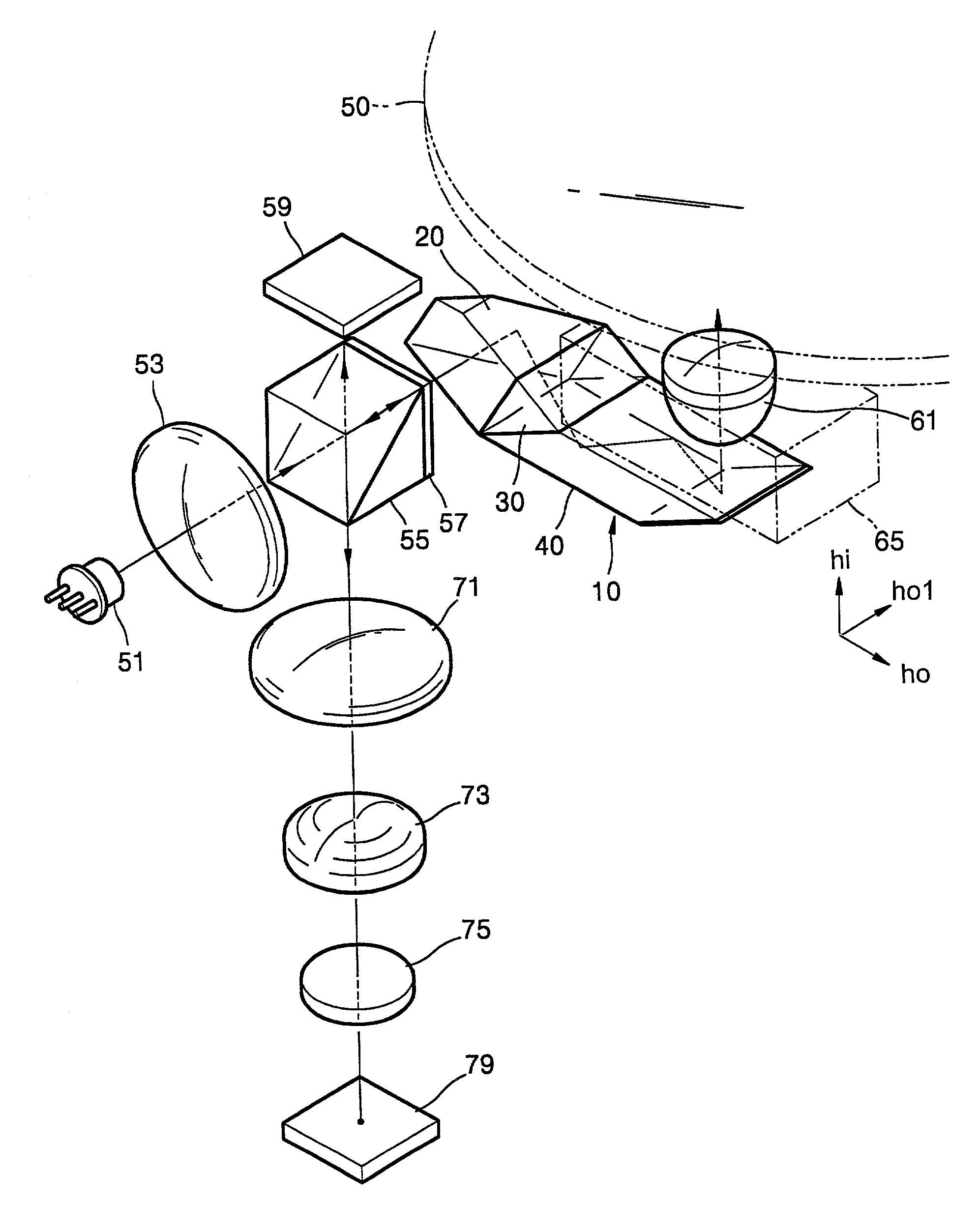
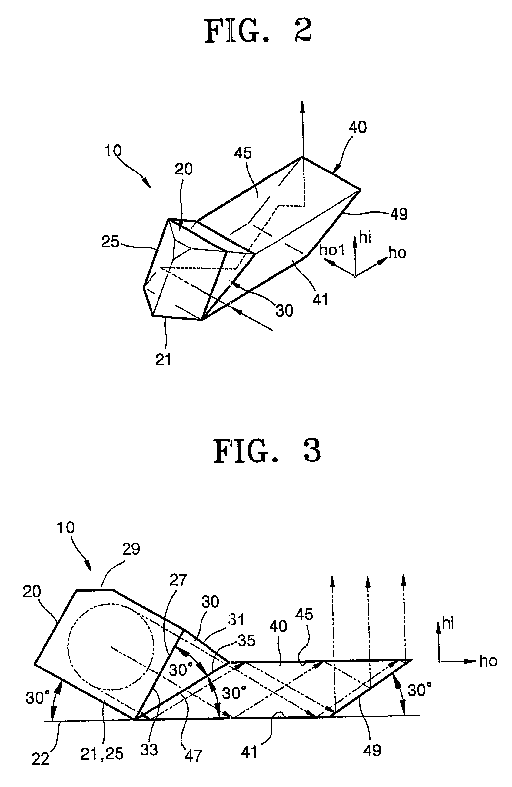
[0033]Referring to FIGS. 2 and 3, a reflection type compound prism 10 according to the present invention comprises first and second prisms 20 and 40. A light beam output from a light source (not shown) substantially parallel to a reference plane (designated by ho and ho1 in FIG. 2), which is perpendicular to a direction of height hi of an optical system, is input to the first prism 20. The size of the light beam with respect to the direction of height hi is reduced by using a difference in an angle between surfaces of the first and second prisms 20 and 40. Then, the light beam is reflected by a surface 49 of the second prism 40 forming an angle less than 45° with respect to the reference plane, and is output in the direction of height hi.

[0034]Here, considering...


PUM


Abstract

A reflection type compound prism and an optical pickup apparatus employing the same. As a light beam is passed through the compound prism, a size of the light beam in a direction perpendicular to a reference plane is reduced by a first reflection surface, propagated toward an objective lens by second and third reflection surfaces and the size restored by reflecting the light beam from a fourth reflection surface forming an angle less than 45° with respect to the reference plane so that a height of an optical system is reducible to obtain a small thin optical pickup with a desired NA. The second and third reflection surfaces are spaced apart in a direction perpendicular to the reference plane by an amount close to a diameter of the light beam at a point of incidence of the light beam with the compound prism.

Description

CROSS REFERENCE TO RELATED APPLICATIONS[0001]This application claims the benefit of Korean Application No. 2001-23343 filed Apr. 30, 2001, in the Korean Patent Office, the disclosure of which is incorporated herein by reference.BACKGROUND OF THE INVENTION[0002]1. Field of the Invention[0003]The present invention relates to a reflection type compound prism which reduces a height of an optical system, and a thin optical pickup apparatus employing the reflection type compound prism.[0004]2. Description of the Related Art[0005]Referring to FIG. 1, a conventional optical pickup apparatus has an optical system in which a light beam emitted from a light source 2 proceeds horizontally, is reflected by a reflection mirror 5 having a reflection surface 5a inclined by 45°, proceeds in a direction of a height h, and is condensed by an objective lens 3 to be focused on an optical disc 1.[0006]A recording density of the optical disc 1 is determined by a size of a light spot formed by the objectiv...

Claims


Application Information

Patent Timeline
IPC IPC(8): G11B7/135G02B5/04G11B7/12G11B7/124G11B7/1356
CPCG02B5/04G11B7/1356G11B7/124G11B7/12
Inventor KIM, DAE-SIKJUNG, SEUNG-TAEYEON, CHEOL-SUNGCHO, KUN-HO
Owner SAMSUNG ELECTRONICS CO LTD
Why Eureka
Try Eureka