Torque applying tool with display window

a technology of torque applying tool and display window, which is applied in the direction of instruments, torque/twisting force measurement, force/torque/work measurement apparatus, etc., can solve the problem that the torque value displayed in the display window is not precise enough to meet the practical needs

Active Publication Date: 2006-08-15
HSIEH CHIH CHING
View PDF11 Cites 3 Cited by
  • Summary
  • Abstract
  • Description
  • Claims
  • Application Information

AI Technical Summary

Problems solved by technology

However, the value of the torque that is displayed in the display window is not precise enough to meet the practical needs.

Method used


Image

  • Torque applying tool with display window
  • Torque applying tool with display window
  • Torque applying tool with display window

Examples


Embodiment Construction

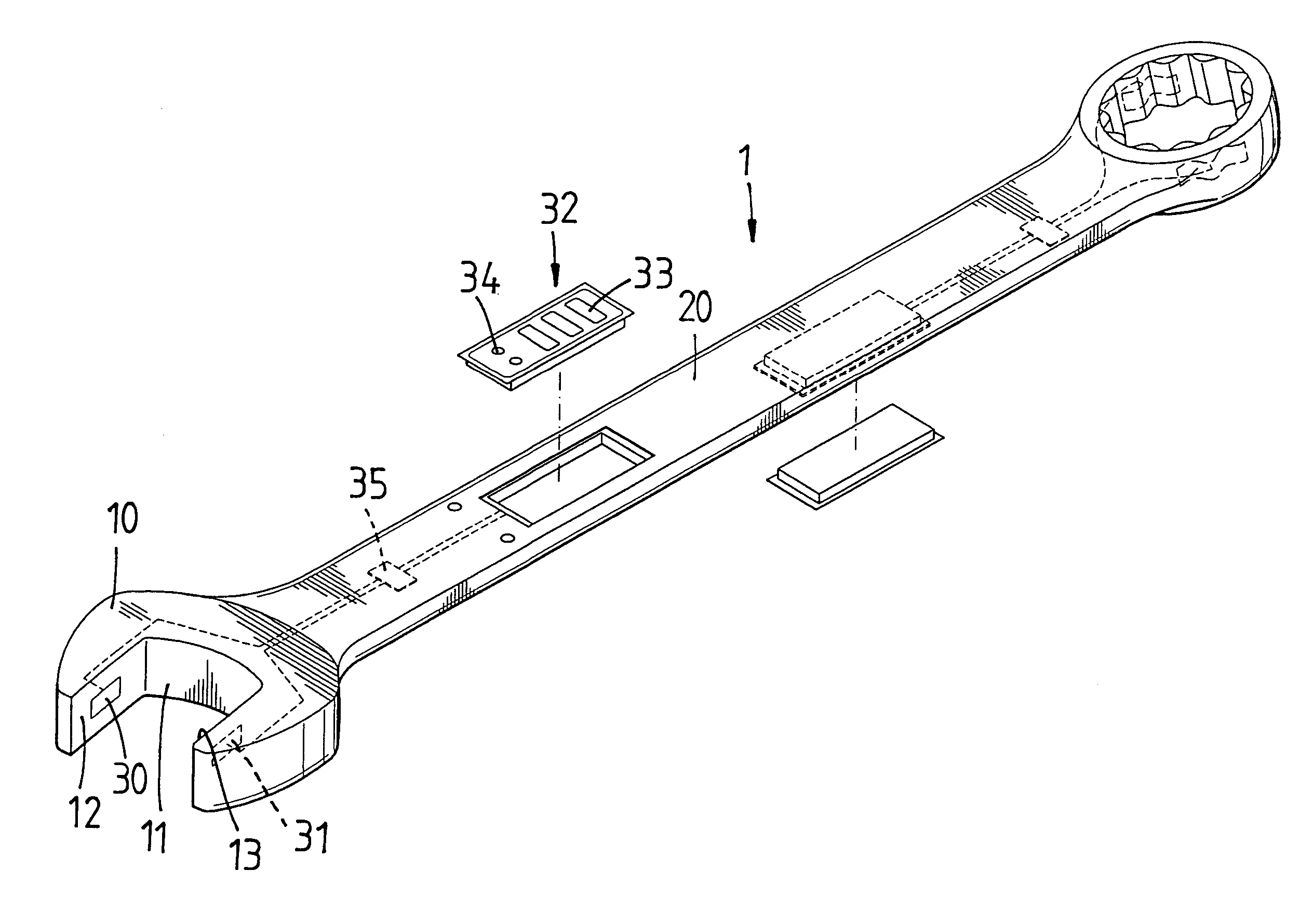
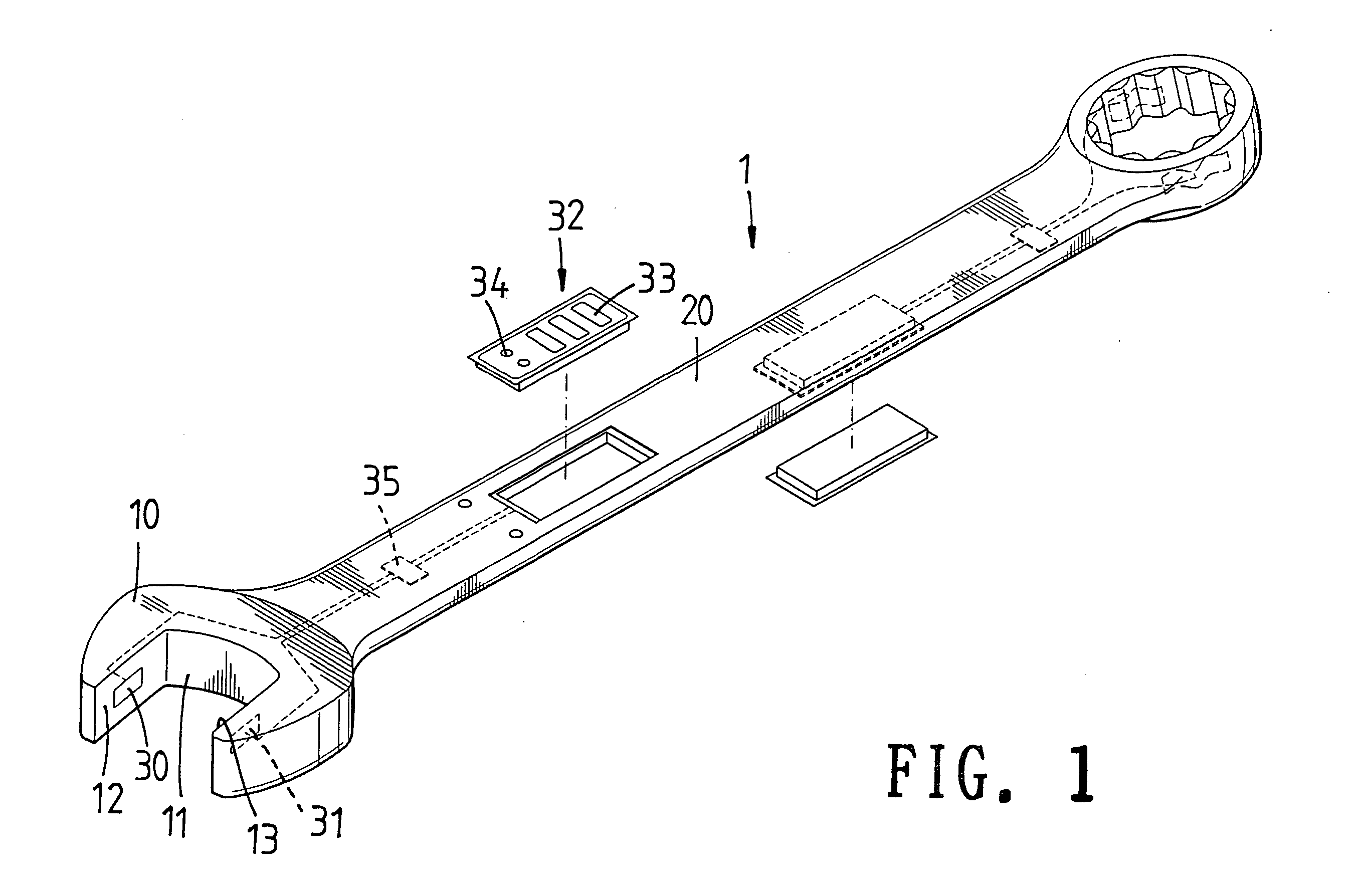
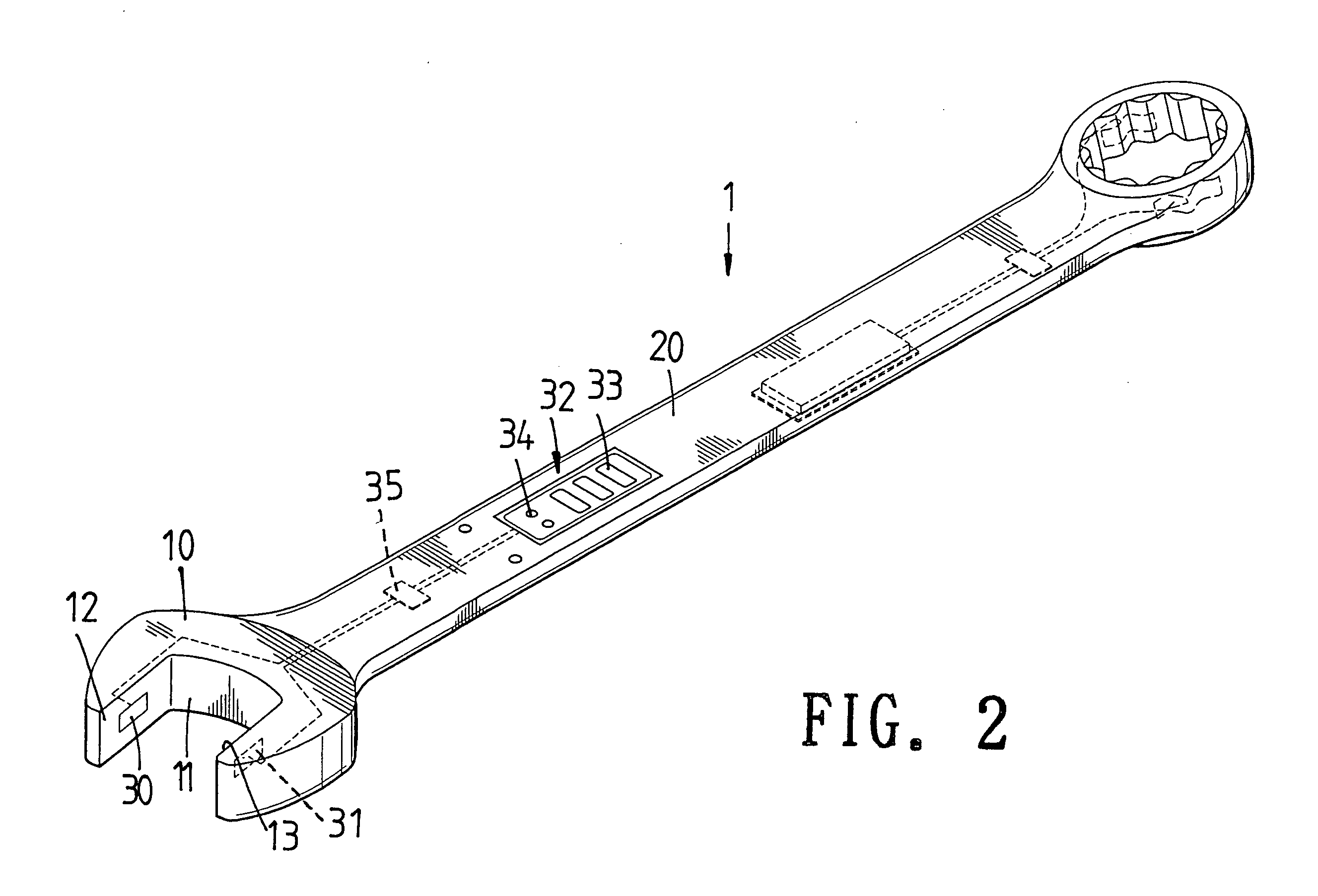
[0012]Referring to FIGS. 1 to 3, a first embodiment of the torque applying tool 1 of the present invention is a wrench which comprises a handle 20 and two function ends are connected to two ends of the handle 20. One of the function ends is an open end which includes two jaws between which an accommodation space 11 is defined. The other function end is a box end. A first resistive strain gauge 30 and a second resistive strain gauge 31 are respectively connected to the two respective insides 12 and 13 of the two jaws. A third resistive strain gauge 35 is connected to the handle 20 and electronically connected to the first and second resistive strain gauges 30, 31. Similarly, the other set of the first, second and third resistive strain gauges are connected to the box end and the handle. Two display units 32 are connected to two opposite sides of the handle 20 and electronically connected to the two respective third resistive strain gauges 35. Each display unit 32 includes a display s...


PUM

PropertyMeasurementUnit
torqueaaaaaaaaaa
forceaaaaaaaaaa
resistanceaaaaaaaaaa

Abstract

A torque applying tool includes a handle and a function end which includes two jaws. A first resistive strain gauge and a second resistive strain gauge are respectively connected to two respective insides of the two jaws. A third resistive strain gauge is connected to the handle and electronically connected to the first and second resistive strain gauges. A display unit is connected to the handle and electronically connected to the third resistive strain gauge. The display unit displays the value of torque that is a result of calculation of information from the resistive strain gauges.

Description

FIELD OF THE INVENTION[0001]The present invention relates to an electronic torque applying tool that chooses one of the two resistive strain gauges that has larger value according to the direction that the tool rotates.BACKGROUND OF THE INVENTION[0002]A conventional electronic wrench is disclosed in U.S. Pat. No. 3,970,155, and includes a handle and a function end such as a box end or two open-ended jaws, two resistive strain gauges are embedded in the tool and located between the function end and the handle. The two resistive strain gauges are electronically connected to a display window which shows the value of the torque that the wrench applies to objects. However, the value of the torque that is displayed in the display window is not precise enough to meet the practical needs. Another conventional electronic wrench is disclosed in U.S. Pat. No. 4,982,612, and includes a handle and a function end such as a box end or two open-ended jaws. A first resistive strain gauge is disposed...

Claims


Application Information

Patent Timeline
Patent Type & Authority Patents(United States)
IPC IPC(8): G01L1/04
CPCG01L5/24
Inventor HSIEH, CHIH-CHING
Owner HSIEH CHIH CHING
Why Eureka
Try Eureka