Universal compound bow press

Inactive Publication Date: 2006-08-15
JOHNSON KENNETH
View PDF10 Cites 21 Cited by
  • Summary
  • Abstract
  • Description
  • Claims
  • Application Information

AI Technical Summary

Benefits of technology

[0018]Several objects and advantages of my invention are;
[0019](a) to provide a portable bow press capable of assisting in the disassembly and assembly of compound bows with either two-piece limbs or single piece limbs.
[0020](b) to provide a

Problems solved by technology

All the devices listed above except Egusquiza's device are described as being limited to assisting in replaces strings and cables.
They are not capable of assisting in the complete assembly, and disassembly of a compound bow.
This is because their adjustment device is limited in travel.
Gissel's device is more limited because it is unable to be used for the maintenance of a compound bow with a broken string.
None of the above devices flex the entire length of the bow's limb.
This adds to the risk of damaging the bow's riser and the limbs, especially when maintaining high powered bows.
Thus making these devices over weight and more costly.
This is a confined area, making it difficult to operate the adjusting device.
Such positioning also increases the risk of the archer being injured while using these devices.
If a string or cable would brake while the archer's is operating these dev

Method used


Image

  • Universal compound bow press
  • Universal compound bow press
  • Universal compound bow press

Examples


Example

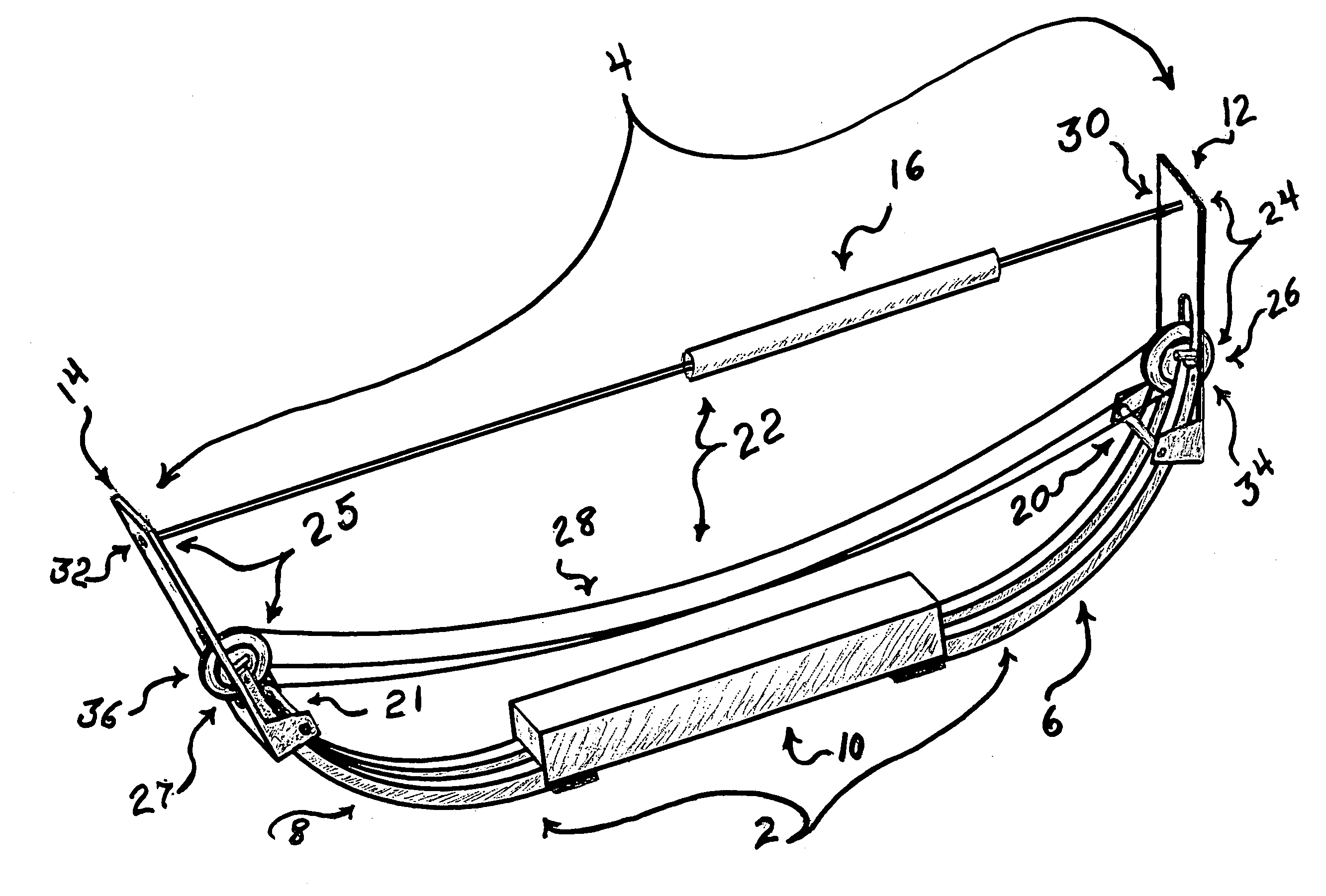
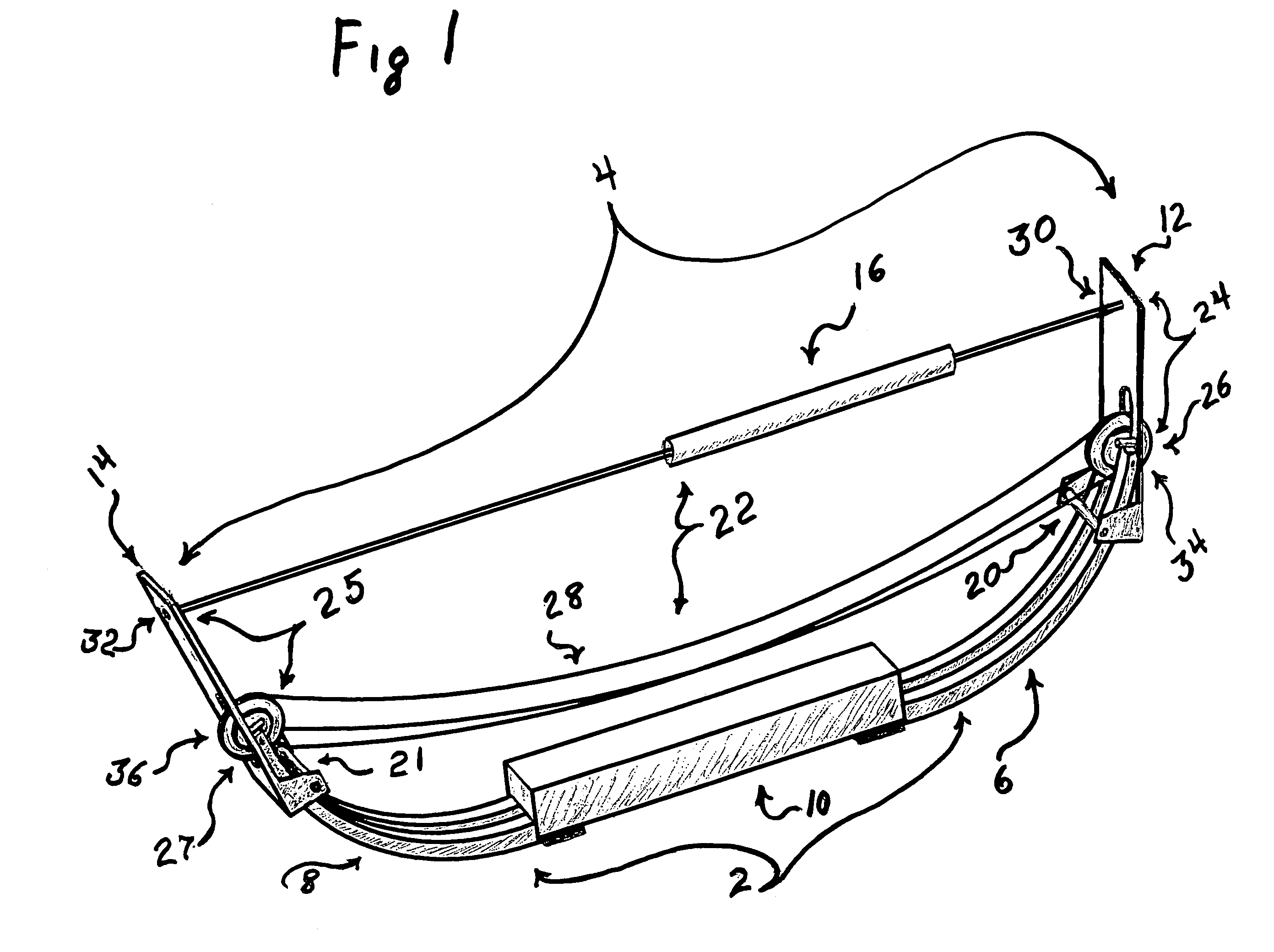
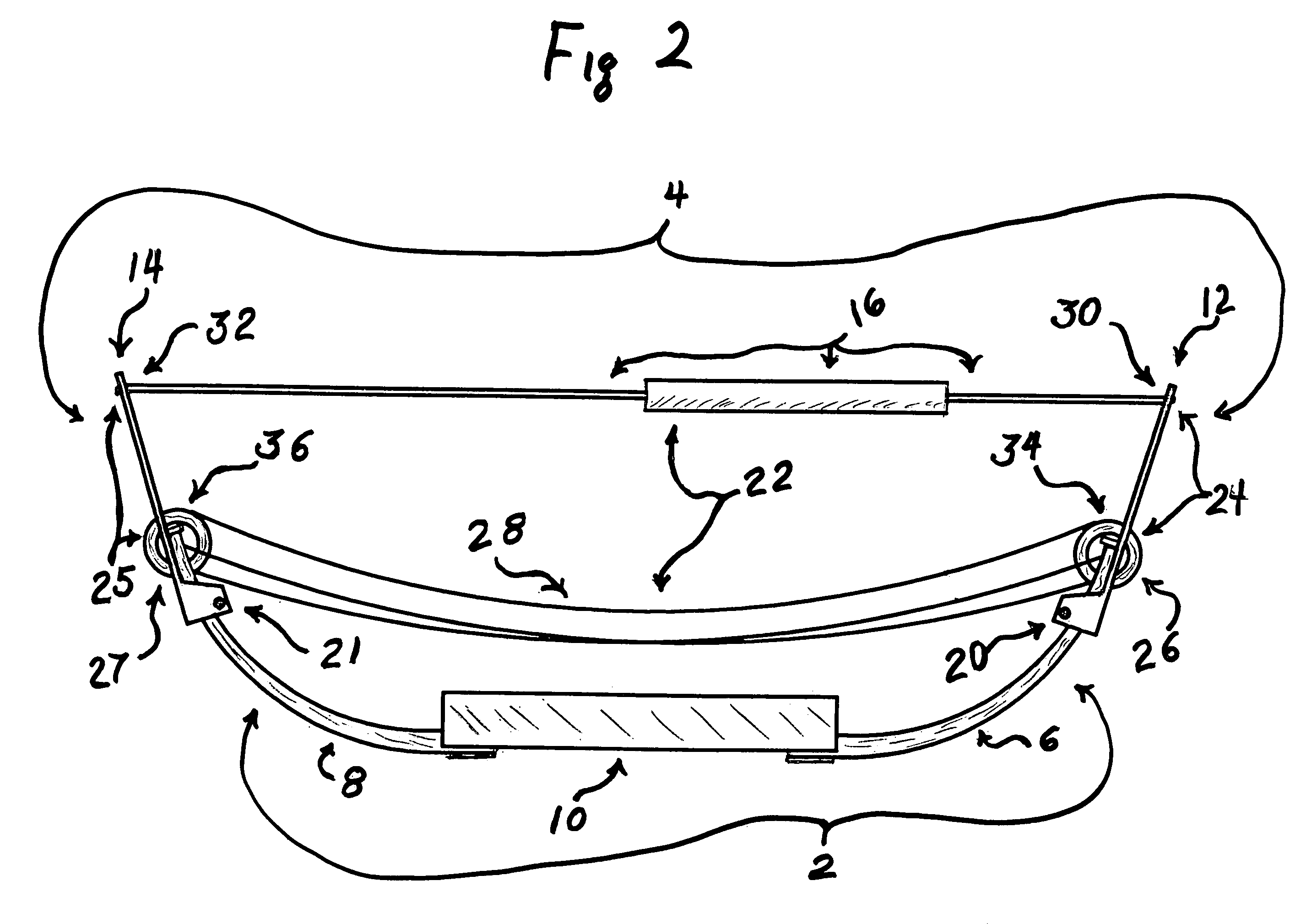
[0056]FIG. 1 shows an isometric view of a portable bow press of this invention 4 attached to a compound bow having two-piece limbs 2. Compound bow 2 having first two-piece limb 6 and the second two-piece limb 8, and riser 10. The compound bow press 4 consisting of first extending member 12, second extending member 14, adjusting device 16, first removable engagement device 20, second removable engagement device 21, first aligning device 34 and second aligning device 36. Extending members are made of a ridged material. Extending member 12 is engaged with the end portion of bow limb 6, using removable engagement device 20 and aligning device 34. Extending member 14 is engaged with the end portion of bow limb 8, using removable engagement device 21 and aligning device 36. Extending member 12 extends beyond the outer end 26 of limb 6. Extending member 14 extends beyond the outer end 27 of limb 8. The engagement of the extending members 12 and 14 are such that, the end portion of first li...


PUM


Abstract

This invention is a inexpensive light weight portable compound bow press that is safer and easier to use. A bow press with a greater mechanical advantage, to be used in the complete maintenance of high powered compound bows having either two piece limbs or one piece limbs. This invention consists of two extending members. Each extending member connects to the outer end of one of the bows limbs, and extend over and away from the outer ends of the bow's first and second limbs. The first end of a liner adjusting apparatus is connected to the first extending member at a central position near the outer edge of the first extending member. The second end of the adjusting apparatus is connected to the second extending member at a central position near the outer edge of the second extending member. This arrangement positions the adjusting apparatus outside and away from the compound bow, allowing for safer and easier use. The adjusting apparatus allows the archer to exert an inward force on the extending members. The extending members apply force to the outer ends of the bow's limbs, thus flexing the entire length of the limb and applying a reduced stress on the bow's riser and limbs. The mechanical advantage provided by the extending members reduces the stress on the adjusting apparatus allowing for the maintenance of high powered bows with lighter weight components. The bow's limbs are flexed inward and locked against their felix action. This way, the bow's string and cables relax and can be removed. The adjusting apparatus can then be reversed until all flex in the bow's limbs is eliminated. The bow press can be removed and the bow can then be disassembled. Assembly of the bow requires reversing this procedure.

Description

BACKGROUND OF THE INVENTION[0001]This invention relates generally to the sport of archery, and more specifically to compound bows. The invention is a portable bow press which allows an archer to relieve the tension on the limbs, string and cables of high powered compound bow having either two-piece limbs or one-piece limbs with greater easy and safety for the archer and less risk of damage to the bow's limbs and riser.PRIOR ART[0002]Paff, U.S. Pat. No. 5,125,389 discloses a tensioning apparatus for tensioning of the limbs of a compound bow with one-piece limbs. Thus enabling the removal and replacement of the compound bow's string and cables. This apparatus uses the same or similar means of connecting to the bow's limbs as Rezmer, U.S. Pat. No. 4,599,987 and Egusquiza, U.S. Pat. No. 5,425,350, and Gissel, U.S. Pat. No. 5,746,192. They use a “T” shaped end, a loop and pin arrangement, or a cord or cable arrangement, that is attached inside the cam grove, at the closed end of single p...

Claims


Application Information

Patent Timeline
IPC IPC(8): F41B5/00F41B5/10F41B5/14
CPCF41B5/1449F41B5/10
Inventor JOHNSON, KENNETH
Owner JOHNSON KENNETH
Why Eureka
Try Eureka