
Ceramic filter with double-blind-groove capacitive coupling structure

A ceramic filter and capacitive coupling technology, which is applied in the field of communication, can solve the problems of difficult capacitive coupling debugging, difficult production and preparation, and poor adjustment accuracy, and achieve the effects of flexible and adjustable blind slot length, simple structure, and convenient design

Inactive Publication Date: 2020-12-04
HUAZHONG UNIV OF SCI & TECH
View PDF3 Cites 1 Cited by
  • Summary
  • Abstract
  • Description
  • Claims
  • Application Information

AI Technical Summary

Problems solved by technology

[0004] Aiming at the defects of the prior art, the object of the present invention is to provide a ceramic filter with a double-blind slot capacitive coupling structure, which aims to solve the difficulty in debugging the capacitive coupling of the existing ceramic filter, the adjustment accuracy is poor, and it is not easy to produce preparation problem

Method used


Image

  • Ceramic filter with double-blind-groove capacitive coupling structure
  • Ceramic filter with double-blind-groove capacitive coupling structure
  • Ceramic filter with double-blind-groove capacitive coupling structure

Examples


Embodiment 1

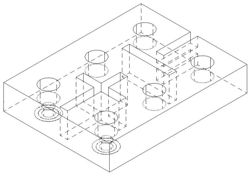
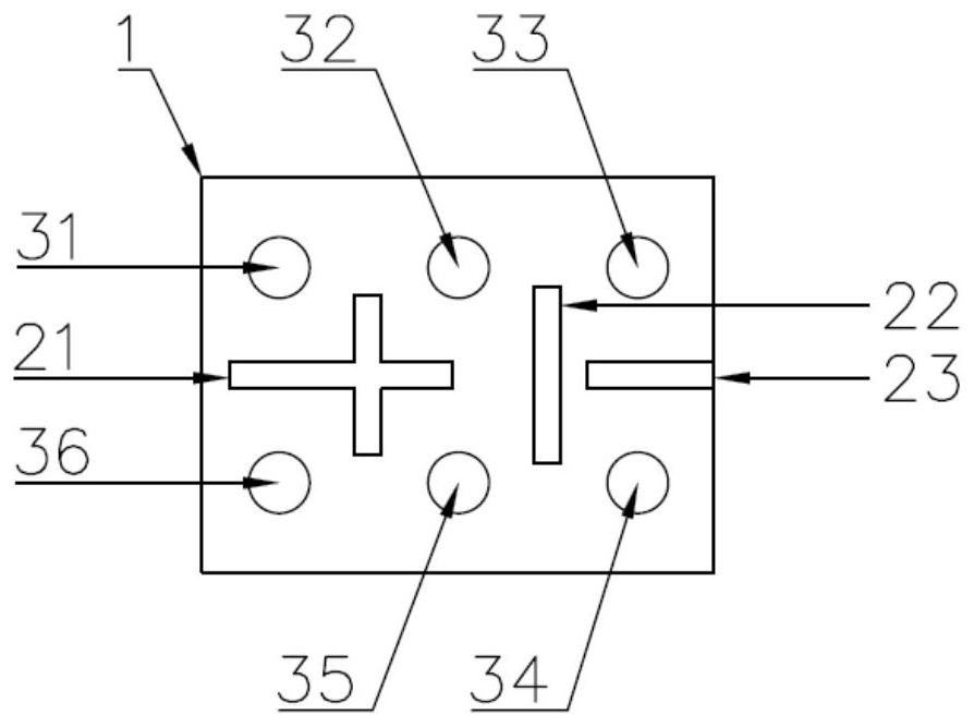
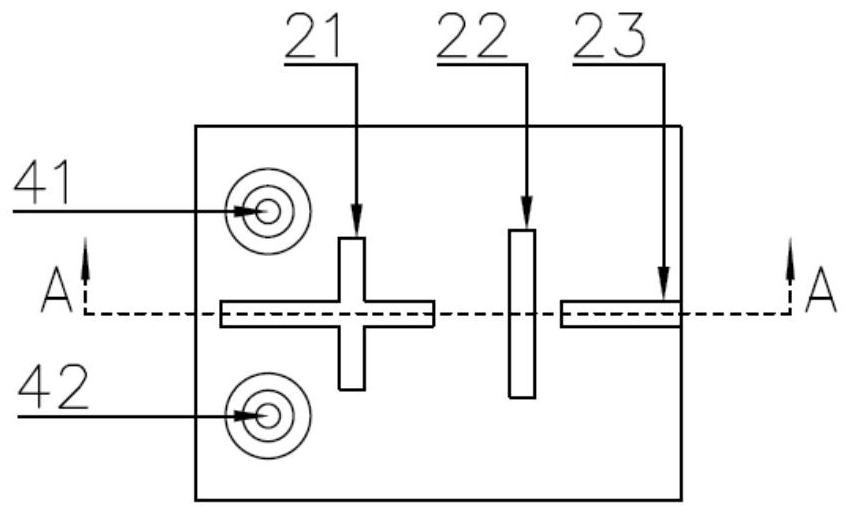
[0026] Such as Figure 1 to Figure 4 As shown, one embodiment of the present invention provides a ceramic filter, including a ceramic filter body 1 with a metal coating on the surface, a tuning hole on the upper surface of the body, a coupling slot and a capacitive coupling structure of double blind slots. There are 6 tuning holes on the upper surface of the ceramic filter body. The tuning holes are blind holes. The tuning holes and part of the body independently form a resonator. The resonant frequency of the resonator can be adjusted by adjusting the depth of the blind holes. The ceramic filter body 1 is provided with a through coupling slot, the coupling slot is a rectangular slot with a set length, width and height, the rectangular slot is located between the tuning holes, and the coupling slots between the tuning holes 31, 32, 35, 36 are connected to form a The cross-shaped structure 21 and the coupling grooves between the tuning holes 32, 33, 34, 35 are connected to form...

Embodiment 2

[0031] Such as Figure 5 to Figure 8 As shown, in another embodiment of the present invention, on the basis of the foregoing content, the capacitive coupling structure 23 is moved from the right end to the left, and is connected with the inline coupling groove 22. The frequency response curve of the filter is as follows Figure 10 shown.


PUM


Abstract

The invention discloses a ceramic filter with a double-blind-groove capacitive coupling structure. The ceramic filter comprises a filter body, tuning holes, a coupling groove, and the capacitive coupling structure composed of an upper blind groove and a lower blind groove, wherein the outer surface of the filter body is provided with a conductive metal coating; the tuning holes are formed in the upper surface of the body; the tuning holes are blind holes; the coupling groove is a rectangular through groove; and the capacitive coupling structure is composed of the upper blind groove and the lower blind groove which are the same in length, width and height, and is located between the two tuning holes. According to the invention, the capacitive coupling structure composed of the upper blind groove and the lower blind groove are arranged between the two tuning holes, and a coupling amount can be changed by adjusting the length and the height of the blind grooves, so capacitive coupling ofthe ceramic filter is realized; the height of one single blind groove is smaller than half of the height of the filter, so blind slot height limitation does not exist; the lengths of the blind groovesare flexible and adjustable, so the debugging difficulty of capacitive coupling of the ceramic filter is effectively reduced, and the debugging precision of capacitive coupling is improved; and the ceramic filter has the characteristics of simple structure, convenience in design, easiness in production and preparation and the like.

Description

technical field [0001] The invention belongs to the technical field of communication, and more specifically relates to a ceramic filter with a double-blind slot capacitive coupling structure. Background technique [0002] With the development of the fifth-generation mobile communication technology, the frequency used for communication is gradually increasing, and the number of filters required increases, which puts forward higher requirements for the size and performance of the filter. Ceramic filters have broad application prospects in the radio frequency field of base stations due to their excellent properties such as low insertion loss and small size. In order to improve the out-of-band rejection, the ceramic filter usually needs to introduce a capacitive coupling structure to form a cross-coupling, and generate a transmission zero near the working frequency band. [0003] In the prior art, the capacitive coupling between the resonators is usually realized by forming dee...

Claims


Application Information

Patent Timeline
Patent Type & Authority Applications(China)
IPC IPC(8): H01P1/20H01P1/207
CPCH01P1/2002H01P1/207
Inventor 梁飞蒙顺良张榕尹宇豪吕文中
Owner HUAZHONG UNIV OF SCI & TECH
Learn More