Connector in which even a narrow card is smoothly guided to a connecting position

a technology of connecting position and card, applied in the field of connecting position, can solve the problem that the card cannot be smoothly guided to a predetermined connecting portion, and achieve the effect of saving spa

Active Publication Date: 2006-08-15
JAPAN AVIATION ELECTRONICS IND LTD
View PDF12 Cites 27 Cited by
  • Summary
  • Abstract
  • Description
  • Claims
  • Application Information

AI Technical Summary

Benefits of technology

[0008]It is still another object of this invention to provide a connector in which a card is smoothly ejecte

Problems solved by technology

However, since the narrow card is guided by the particular mechanism having the rotary member to the left

Method used


Image

  • Connector in which even a narrow card is smoothly guided to a connecting position
  • Connector in which even a narrow card is smoothly guided to a connecting position
  • Connector in which even a narrow card is smoothly guided to a connecting position

Examples


Embodiment Construction

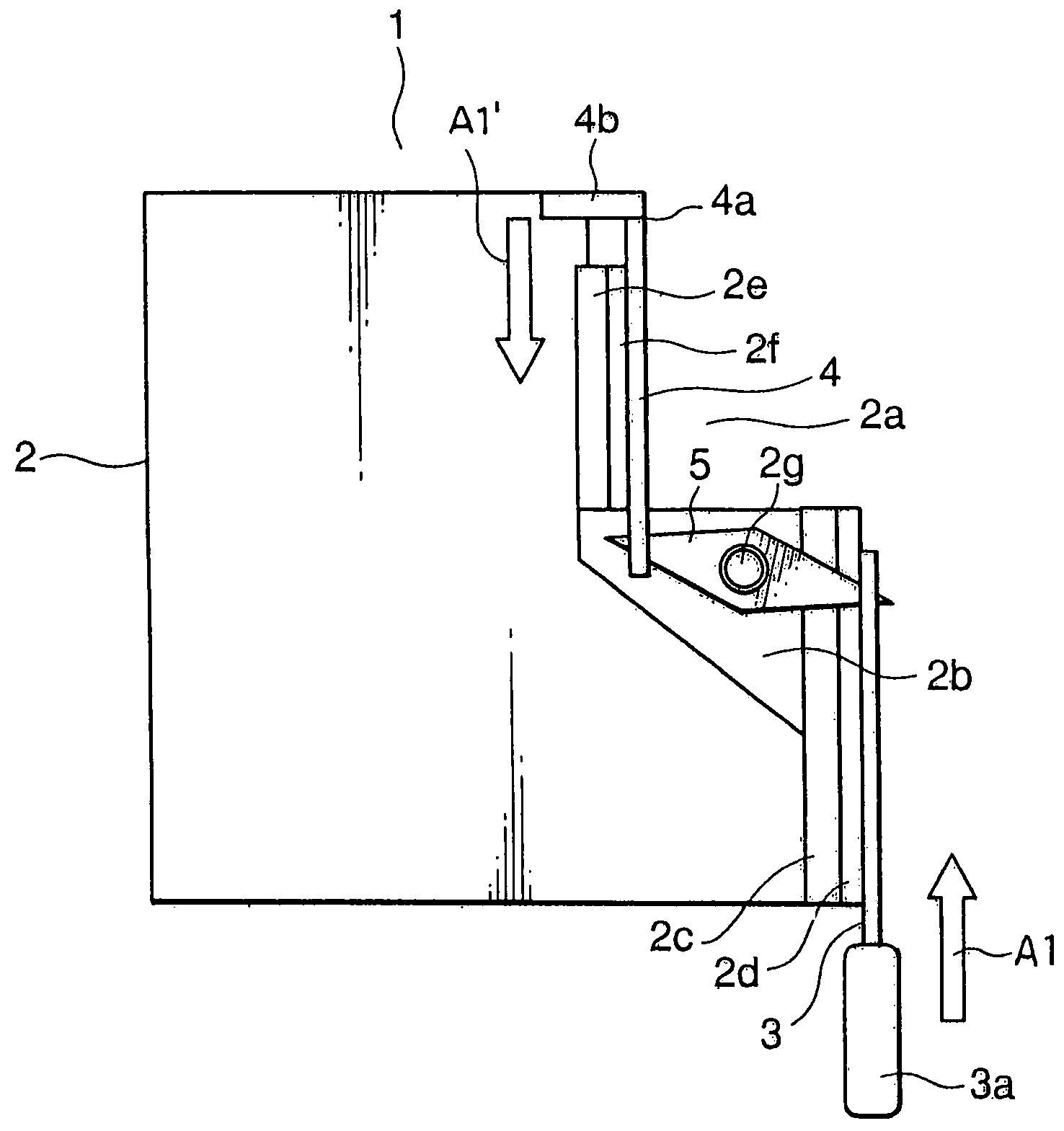
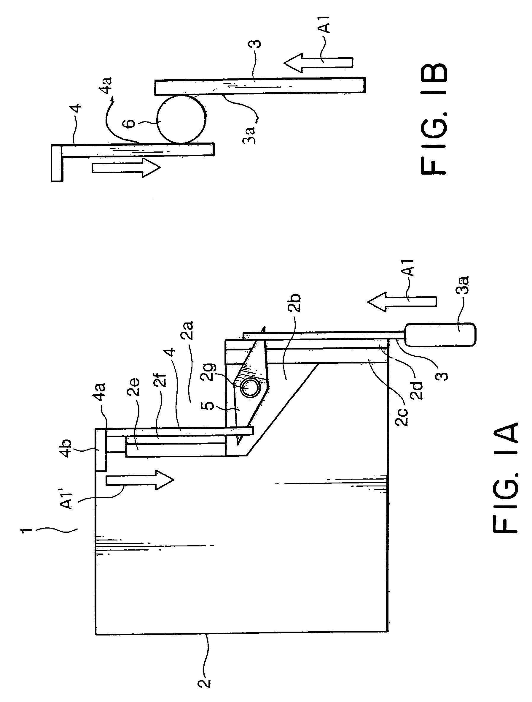
[0051]Referring to FIG. 1A, description will be made of a card connector (hereinafter simply be referred to as a “connector”) according to an embodiment of this invention.

[0052]As will be understood from the following description, the connector depicted at 1 in the figure uses a rotary lever mechanism and has a rectangular housing 2. The housing 2 has a rectangular cutout portion 2a formed at a right upper corner thereof, a guide space 2b formed under the cutout portion 2a to guide a first card, and a first guide wall 2c and a first slide guide 2d which are formed on the right side of the guide space 2b. In parallel to the first slide guide 2d, a first eject bar 3 is arranged to be slidable. The first eject bar 3 has an operation button 3a.

[0053]The housing 2 is provided with a second guide wall 2e and a second slide guide 2f which are formed on its right side surface adjacent to the cutout portion 2a. In parallel to the second slide guide 2f, a second eject bar 4 is arranged to be...


PUM


Abstract

In a connector adapted to be selectively connected to two types of cards inserted towards an insertion direction and different from each other in width thereof, a housing defines a guide space and has a guide portion for guiding an insertion of a selected one of the cards. The guide portion extends in the guide space in a particular direction intersecting the insertion direction. An eject mechanism is provided for moving the selected one towards a removing direction opposite to the first direction. The eject mechanism includes an eject member to be engaged with the selected one and moved together with the selected one, an operating member for moving the eject member towards the removing direction, and a rotary member having a rotation center and rotatable around the rotation center to transmit operation of the operating member to the eject member. The rotation center is disposed in the guide space.

Description

[0001]This application claims priority to prior Japanese application JP 2005-41003, the disclosure of which is incorporated herein by reference.BACKGROUND OF THE INVENTION[0002]This invention relates to a connector connectable selectively to two types of cards different in width.[0003]For example; a card called an express card is used as an object to be connected to the connector. The express card is produced in accordance with a card standard defined by PCMCIA (Personal Computer Memory Card International Association) and has two types including a narrow card / 34 module and a wide card / 54 module. Therefore, a connector used for connection of the express card is desired to be connectable to both of the two types of cards.[0004]For example, a connector of the type is disclosed in Japanese Unexamined Patent Application Publication (JP-A) No. 2004-318511 and has a housing adapted to receive a card to be inserted therein. The housing has a left insertion space and a right insertion space....

Claims


Application Information

Patent Timeline
IPC IPC(8): H01R24/00
CPCG06K7/0034G06K13/08G06K13/0806Y10S439/923H01R13/635H01R27/00H01R12/71
Inventor NAKAMURA, KEISUKE
Owner JAPAN AVIATION ELECTRONICS IND LTD
Why Eureka
Try Eureka