Wheel transmission

Inactive Publication Date: 2006-08-15
JUNGHEINRICH AG
View PDF12 Cites 12 Cited by
  • Summary
  • Abstract
  • Description
  • Claims
  • Application Information

AI Technical Summary

Benefits of technology

[0026]The present invention relates to another improved wheel transmission of an improved wheel transmission (Korean Paten Application No. 2001–11280) developed on the basis of the above-mentioned wheel transmission (Korean Patent Application No. 2000–46795), and an object of the present invention is to provide a wheel transmission capable of achieving the same effect as that of a conventional wheel transmission although change clutch parts are disposed to one side in contrast to a conventional wheel transmission in which change clutch parts are separately provided to both sides.

Problems solved by technology

However, the above-mentioned conventional transmission applied to a heavy construction vehicle such as a forklift truck has disadvantages in that there is a long distance between an engine and an axle shaft because the transmission together with a clutch are placed between a torque converter and an axle shaft, much of vibration and noise generated from the engine is transferred to a driver's seat located at the center of the heavy vehicle through the transmission, and it is difficult for a user to operate the heavy vehicle at a narrow site because the heavy vehicle must be configured to be long due to the transmission.
Hence, it is difficult to operate at narrow site, and also its operating behavior is relatively slow.
Since a heavy construction vehicle equipped with a transmission having a conventional configuration includes a large-sized housing adapted to receive a clutch and a transmission, there are drawbacks in that it is impossible to freely design the center part of the vehicle and it is possible to achieve a satisfactory reduction ratio only where a final reduction gear intended to finally reduce an engine speed is designed to have a large size.

Method used


Image

  • Wheel transmission
  • Wheel transmission
  • Wheel transmission

Examples


Embodiment Construction

[0062]This invention will be described in further detail by way of example with reference to the accompanying drawings.

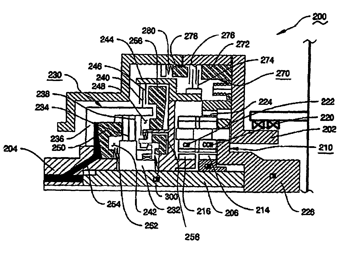
[0063]FIG. 6 is an exploded perspective view of an improved wheel transmission according to the present invention, and FIG. 7 is a cross-sectional view showing an assembled condition of components of FIG. 6.

[0064]FIG. 8 is a cross-sectional view showing an improved wheel transmission according to the present invention, FIG. 9a is an enlarged view of “B” portion of FIG. 8 in a forward drive operation, and FIG. 9b is view of a planetary gear assembly of the wheel transmission according to the present invention in a forward drive operation.

[0065]FIG. 10a is an enlarged view of “B” portion of FIG. 8 in a reverse travel,

[0066]FIG. 10b shows the planetary gear assembly according to the present invention in a reverse travel, and FIG. 10c is an enlarged view of “C” portion of FIG. 10a which shows a one-way clutch.

[0067]FIG. 11 is a view showing an improved wheel transmissio...


PUM


Abstract

A wheel transmission for a heavy construction vehicle, which can be applied to specially-equipped vehicles as well as heavy construction vehicles such as a forklift truck and a mechanical shovel. The wheel transmission (200) is intended to drive a pair of right and left wheels independently, and includes a planetary gear assembly (210), a change clutch part (230), a one-way clutch part (300), and a brake part (270) housed in an axle hub at which opposite ends of a drive axle shaft are located, turning force from an engine of a heavy construction vehicle being transferred to the drive axle shaft through a torque converter, a driving shaft, a final reduction gear and a differential gear.

Description

TECHNICAL FIELD[0001]The present invention relates to a wheel transmission for a heavy construction vehicle which can be applied to specially-equipped vehicles as well as heavy construction vehicles such as a forklift truck and a mechanical shovel, and more particularly to a wheel transmission for a heavy construction vehicle which is adapted to be mounted on an axle hub to enable shifting to a forward drive stage and a reverse stage and is provided with shifting a clutch part, a brake part and the like, and which is intended to separately control forward and reverse drives of both drive wheels to allow turning in place.BACKGROUND ART[0002]In general, heavy construction vehicles use hydraulic motors or engines as their power source, and are classified into wheel type and crawler type according to means of mobility.[0003]Although a heavy construction vehicle is not intended to travel at a high speed and does not require multistage shifting, the heavy construction vehicle has essentia...

Claims


Application Information

Patent Timeline
IPC IPC(8): F16H31/00B60T1/06B60K17/00B60K17/02B60K17/04B60K17/26B66F9/075F16D55/40F16D63/00F16H3/62F16H48/06
CPCB60K17/02B60K17/046B66F9/07572B66F9/07509B60K17/26B60K17/00
Inventor HAN, SEUNG-WOO
Owner JUNGHEINRICH AG
Why Eureka
Try Eureka