High-speed high-stand fabric take-up device with uniform fabric tautness arrangement

Active Publication Date: 2006-08-22
PAI LUNG MACHINERY MILL CO LTD
View PDF5 Cites 3 Cited by
  • Summary
  • Abstract
  • Description
  • Claims
  • Application Information

AI Technical Summary

Benefits of technology

[0004]It is therefore an object of the present invention to provide a high-speed high-stand fabric take-up device. In a fabric take-up process, an angle of a friction rod from its initial inoperative position to its maximum operating position is much less than that of the prior art. This is because the weight of the whole friction rod is applied on fabric being woun

Problems solved by technology

It is not widely employed due to its small capacity.
Thus, fabric tends to throw away in the winding process.
However, the patent still has a drawback as detailed below by referring to FIGS. 1A and 1B

Method used


Image

  • High-speed high-stand fabric take-up device with uniform fabric tautness arrangement
  • High-speed high-stand fabric take-up device with uniform fabric tautness arrangement
  • High-speed high-stand fabric take-up device with uniform fabric tautness arrangement

Examples


Example

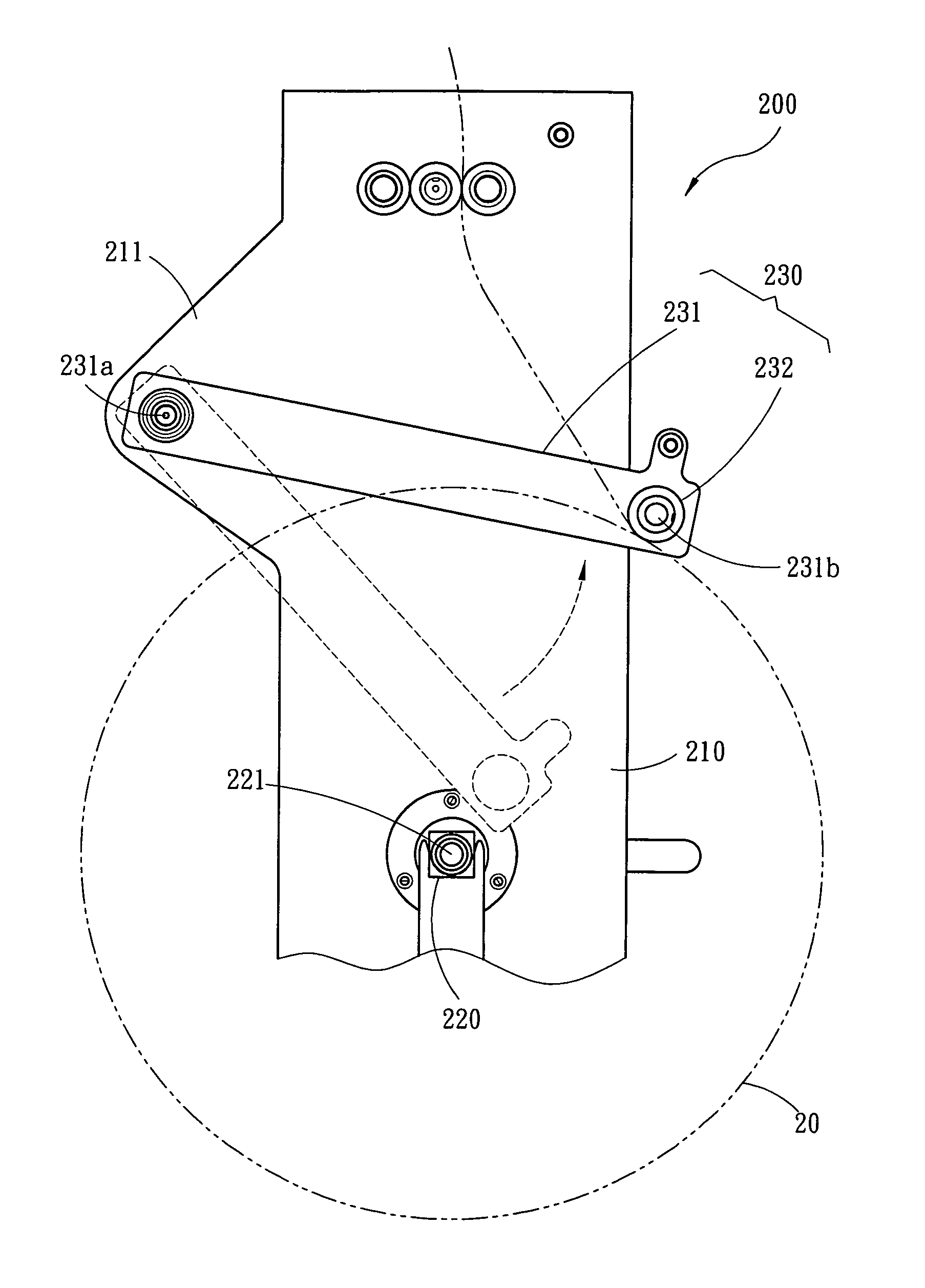
[0012]Referring to FIGS. 2, 3 and 4, a high-speed high-stand fabric take-up device 200 of high capacity in accordance with a preferred embodiment of the invention comprises two side boxes 210, a take-up shaft 220, a friction mechanism 230, a speed change mechanism 240, a first transmission assembly 250, a second transmission assembly 260, a third transmission assembly 270, a fourth transmission assembly 280, and a supply mechanism 290. Each component is discussed in detail below.

[0013]Please refer to FIG. 2. A triangular projection 211 is formed on a side of the side box 210 proximate its top. The take-up shaft 220 is provided across intermediate portions of the side boxes 210. The take-up shaft 220 is adapted to wind fabric therearound. The friction mechanism 230 is of U-shaped and comprises two arms 231 each having the other end 231a pivotably connected to the projection 211, and a friction rod 232 fixedly interconnected one ends 231b of the arms 231. The friction rod 232 is dispo...


PUM


Abstract

Provided is a high-speed high-stand device for taking up fabric comprising two side boxes each including a projection formed on its side proximate top; a take-up shaft provided across intermediate portions of the side boxes, the take-up shaft being adapted to wind fabric therearound; and a friction mechanism including two arms each having the other end pivotably connected to the projection, and a friction rod fixedly interconnected one ends of the arms, the friction rod being provided above the take-up shaft to contact the fabric wound therearound. In a fabric take-up process, an angle from an initial position of the arms to an operating position thereof is limited as a diameter of the fabric is increasing, and a pressing force exerted by the friction rod on the fabric being wound around the take-up shaft is the same for obtaining a uniform tautness of the wound fabric.

Description

FIELD OF THE INVETNION[0001]The present invention relates to fabric take-up devices and more particularly to a high-speed high-stand fabric take-up device having an arrangement for applying same pressing force on fabric being wound around a take-up shaft such that a fabric roll with uniform tautness can be obtained around the shaft.BACKGROUND OF THE INVENTION[0002]In a knitting machine, a take-up device is typically employed to wind fabric in rolls. One type of take-up device can wind fabric in rolls having a diameter of about 20 inches. It is not widely employed due to its small capacity. The other type of take-up device, as the widely employed one due to it high capacity, can wind fabric rolls having a diameter of about 46 inches (i.e., fabric weight more than 100 kg). However, for the latter one centrifugal force increases as fabric is winding on a take-up shaft. Further, fabric is pliable in nature. Thus, fabric tends to throw away in the winding process.[0003]U.S. Pat. No. 6,63...

Claims


Application Information

Patent Timeline
IPC IPC(8): D04B15/88
CPCD04B15/88
Inventor CHEN, SHIH-CHI
Owner PAI LUNG MACHINERY MILL CO LTD
Why Eureka
Try Eureka