Multi-pin pin seam for an industrial fabric

a multi-pin, industrial fabric technology, applied in the field of industrial fabrics, can solve the problems of discontinuity on the fabric surface, inability to use plastic monofilaments, and inability to meet the needs of production, so as to reduce or minimize discontinuity, reduce or minimize the risk of abrasion in the seam area, and reduce or eliminate the effect of discontinuity

Active Publication Date: 2006-08-22
ALBANY INT CORP
View PDF20 Cites 4 Cited by
  • Summary
  • Abstract
  • Description
  • Claims
  • Application Information

AI Technical Summary

Benefits of technology

[0018]Accordingly, the present invention relates to a multi-pin pin seam used to join a woven fabric wherein seaming loops are made around three or more pins or pintles. Advantageously, this arrangement results in the seam area having a weave pattern which more closely conforms to the fabric body, so as to reduce or minimize discontinuity and thus reduce or minimize marking of the product thereon with the risk of abrasion in the seam area reduced or eliminated.

Problems solved by technology

Generally, these fabrics are woven from plastic monofilament, although metal wire may be used instead of plastic monofilament when, for example, temperature conditions during a nonwovens manufacturing process make it impractical or impossible to use plastic monofilament.
This is because the fibrous web being produced is extremely susceptible to defects such as marking by any nonuniformity in the fabric or fabrics.
This dissimilarity between the weave of the fabric body and that of the seam area results in a discontinuity on the fabric surface.
This discontinuity is also shown in FIG. 2B (cross sectional view), and unfortunately, can lead to marking of a product carried on the fabric or abrasion of the seam area of the fabric by stationary elements 10 during use.
In some instances alternative rows of MD yarns 14 can form differing loop lengths and geometries resulting in dissimilarities between the seam and the body of the fabric.
As mentioned above, this dissimilarity between the weave of the fabric body and that of the seam area results in a discontinuity on the fabric surface.
As previously mentioned, this discontinuity can lead to marking of a product carried on the fabric or abrasion of the fabric seam itself by stationary objects.

Method used


Image

  • Multi-pin pin seam for an industrial fabric
  • Multi-pin pin seam for an industrial fabric
  • Multi-pin pin seam for an industrial fabric

Examples


Embodiment Construction

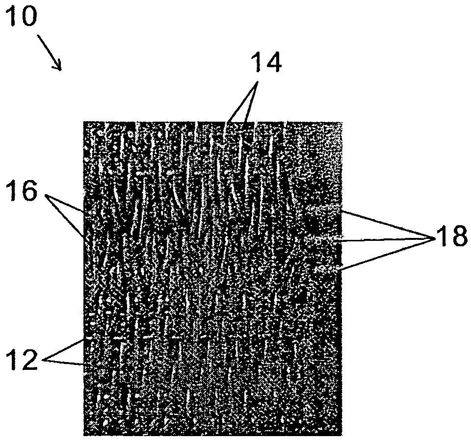
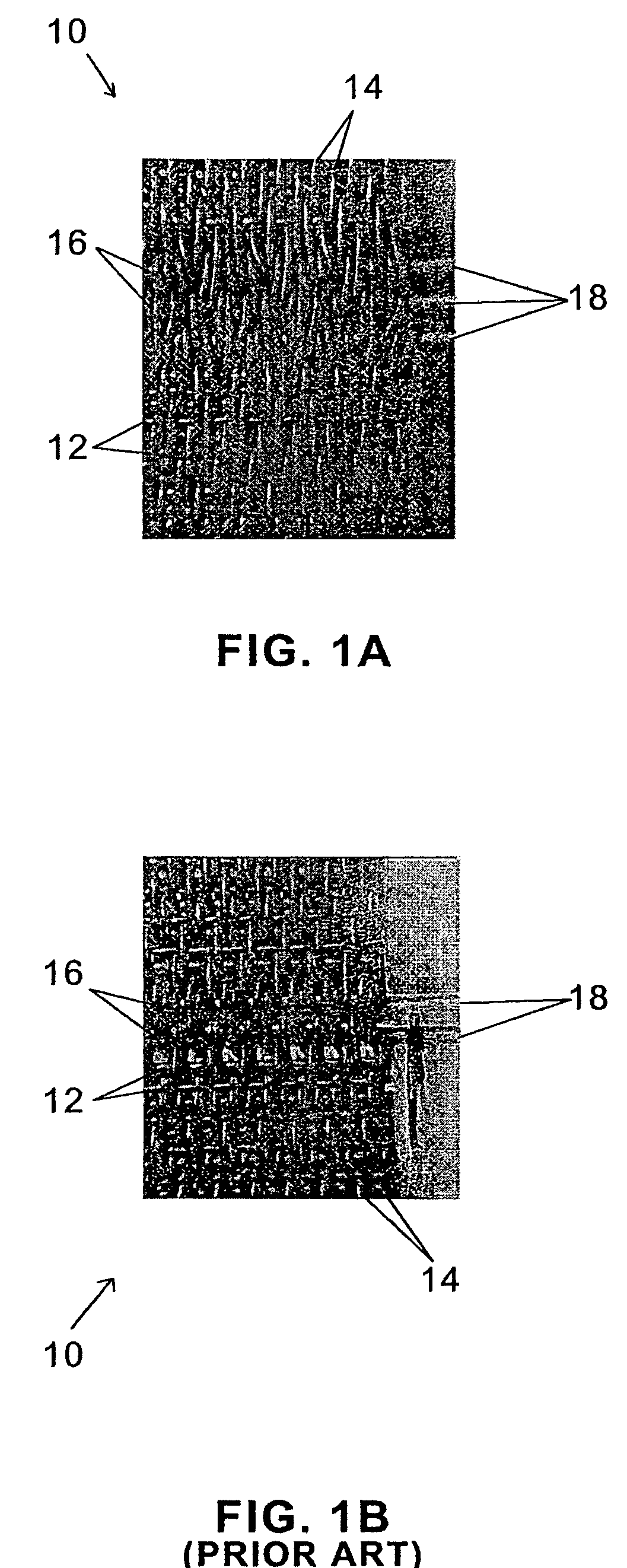
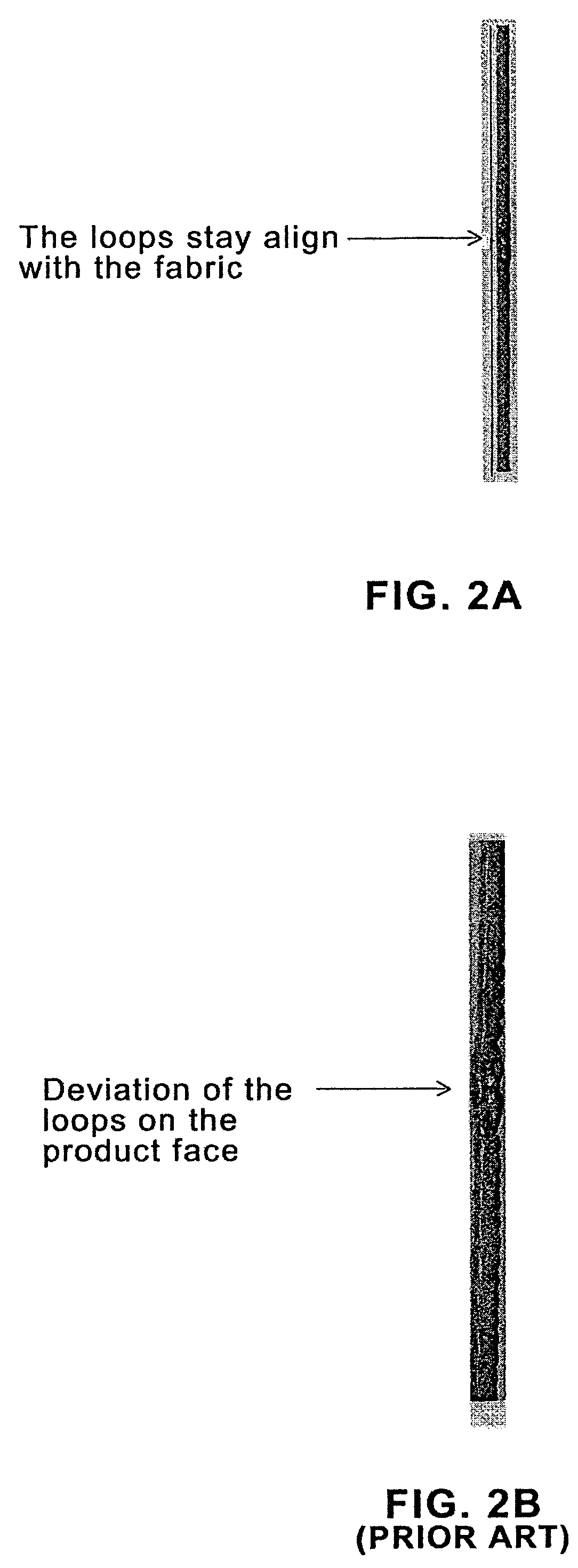
[0030]Referring now more specifically to the drawing figures, one embodiment of the invention is shown in FIG. 1A (plan view), FIG. 2A (cross section), and FIGS. 3C–3E (cross section). In general, the triple pin seam illustrated in these figures results in less of a discontinuity on the surface of the fabric 10, compared with the prior art double pin seam. This is clearly illustrated in a comparison of FIG. 2A to FIG. 2B, which show seaming loops that stay aligned in FIG. 2A and seaming loops that deviate from the fabric face in FIG. 2B. Accordingly in FIG. 2A the weave pattern in the seam area conforms more closely to that in the rest of the fabric 10 than that practiced in the prior art. Consequently, marking of a product transported on the fabric 10 and abrasion to the fabric in the seam area as it passes over stationary elements when in use, is reduced or eliminated.

[0031]As seen in FIG. 1A, the fabric 10 according to the invention comprises a plurality of rows of MD yarns 14 in...


PUM


Abstract

The present invention relates to a multi-pin pin seam used to join the a woven fabric wherein the loops are made around three or more cross-machine CD pins or pintles. Advantageously, this arrangement results in the seam area having a weave pattern that more closely conforms to that of the fabric body, and thus the risk of sheet marking and / or fabric abrasion in the seam area is reduced or eliminated.

Description

BACKGROUND OF THE INVENTION[0001]1. Field of the Invention[0002]The present invention relates to industrial fabrics. More particularly, the invention relates to a multi-pin seam for a woven fabric wherein the weave pattern in the seam area more closely conforms to that in the weave pattern in the fabric body.[0003]2. Description of the Related Art[0004]The production of nonwoven fabrics is well known in the art. Such fabrics are produced directly from fibers without conventional spinning, weaving or knitting operations. Instead, they may be produced by spun-bonding or melt-blowing processes in which newly extruded fibers are laid down to form a web while still in a hot, tacky condition following extrusion, whereby they adhere to one another to yield an integral nonwoven web.[0005]Nonwoven product may also be produced by air-laying or carding operations where the web of fibers is consolidated, subsequent to deposition, into a nonwoven product by needling or hydroentanglement. In the ...

Claims


Application Information

Patent Timeline
Patent Type & Authority Patents(United States)
IPC IPC(8): D21F7/08
CPCD21F1/0054D03D3/04D21F7/08
Inventor CANON, LUCMONNERIE, JEAN-LOUIS
Owner ALBANY INT CORP
Why Eureka
Try Eureka