Systems and methods for measuring radiated thermal energy during an additive manufacturing operation

a technology of additive manufacturing and measuring system, applied in the direction of additive manufacturing process, manufacturing tool, welding/soldering/cutting article, etc., can solve the problem of difficult to avoid at least slight variations in size and temperature, and achieve the effect of reducing or minimizing discontinuities, high travel rate, and long additive machining process

Pending Publication Date: 2020-09-17
DIVERGENT TECH INC
View PDF14 Cites 1 Cited by
  • Summary
  • Abstract
  • Description
  • Claims
  • Application Information

AI Technical Summary

Benefits of technology

This patent text describes a method to create parts using a process called additive manufacturing. In this process, layers of powder are added to a part and melted using a laser to create a molten region that solidifies to form the part. However, there can be variations in the size and temperature of the molten region as different layers are added. These variations can cause discontinuities in the final part. This patent aims to reduce or minimize these discontinuities by controlling the process in real-time to make it more stable and reliable.

Problems solved by technology

As additive machining processes can be lengthy and include any number of passes of the melt pool, it can be difficult to avoid at least slight variations in the size and temperature of the melt pool as the melt pool is used to solidify the part.

Method used


Image

  • Systems and methods for measuring radiated thermal energy during an additive manufacturing operation
  • Systems and methods for measuring radiated thermal energy during an additive manufacturing operation
  • Systems and methods for measuring radiated thermal energy during an additive manufacturing operation

Examples


Embodiment Construction

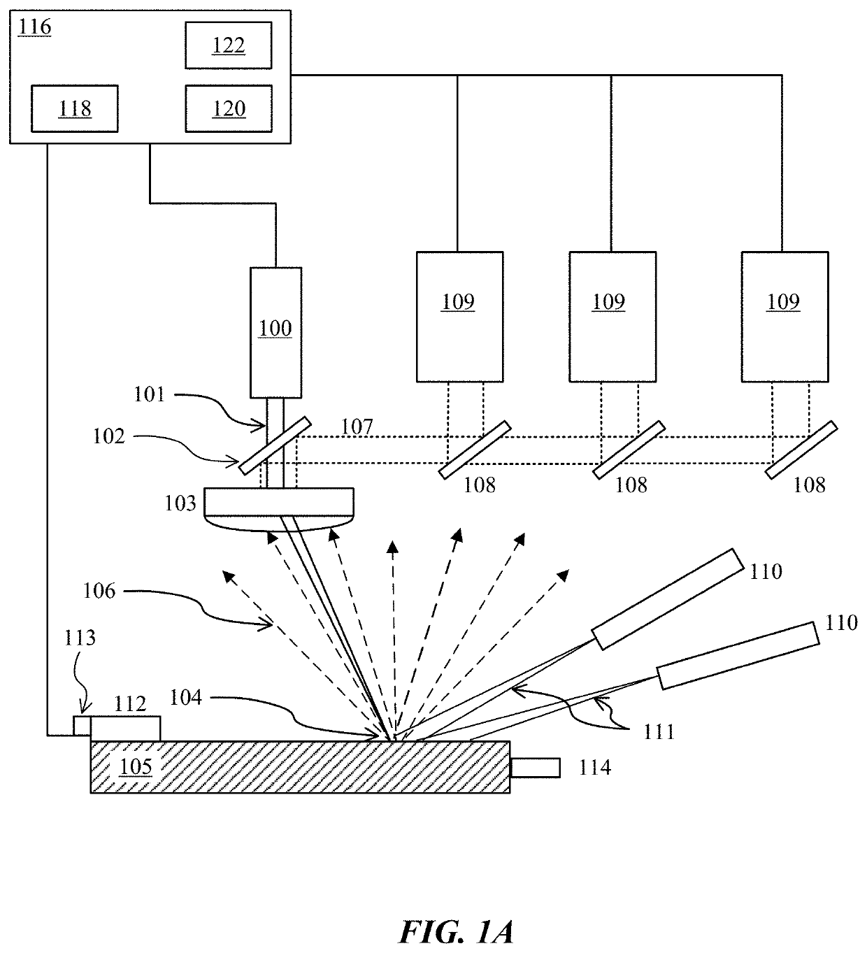
[0043]FIG. 1A shows an embodiment of an additive manufacturing system that uses one or more optical sensing apparatus to determine the thermal energy density. The thermal energy density is sensitive to changes in process parameters such as, for example, energy source power, energy source speed, and hatch spacing. The additive manufacturing system of FIG. 1A uses a laser 100 as the energy source. The laser 100 emits a laser beam 101 which passes through a partially reflective mirror 102 and enters a scanning and focusing system 103 which then projects the beam to a small region 104 on the work platform 105. In some embodiments, the work platform is a powder bed. Optical energy 106 is emitted from the small region 104 on account of high material temperatures.

[0044]In some embodiments, the scanning and focusing system 103 can be configured to collect some of the optical energy 106 emitted from the beam interaction region 104. The partially reflective mirror 102 can reflect the optical ...


PUM

PropertyMeasurementUnit
wavelengthaaaaaaaaaa

Abstract

This disclosure describes various methods and apparatus for characterizing an additive manufacturing process. A method for characterizing the additive manufacturing process can include generating scans of an energy source across a build plane; measuring an amount of energy radiated from the build plane during each of the scans using an optical sensing system that monitors two discrete wavelengths associated with a blackbody radiation curve of the layer of powder; determining temperature variations for an area of the build plane traversed by the scans based upon a ratio of sensor readings taken at the two discrete wavelengths; determining that the temperature variations are outside a threshold range of values; and thereafter, adjusting subsequent scans of the energy source across or proximate the area of the build plane.

Description

CROSS-REFERENCES TO RELATED APPLICATIONS[0001]This application is a continuation of U.S. patent application Ser. No. 16 / 282,004, filed Feb. 21, 2019; which claims priority to U.S. Provisional Patent Application No. 62 / 743,391, filed on Oct. 9, 2018, to U.S. Provisional Patent Application No. 62 / 643,457 filed on Mar. 15, 2018 and to U.S. Provisional Patent Application No. 62 / 633,487, filed on Feb. 21, 2018, the disclosures of which are hereby incorporated by reference in their entirety for all purposes.BACKGROUND OF THE INVENTION[0002]Additive manufacturing, or the sequential assembly or construction of a part through the combination of material addition and applied energy, takes on many forms and currently exists in many specific implementations and embodiments. Additive manufacturing can be carried out by using any of a number of various processes that involve the formation of a three dimensional part of virtually any shape. The various processes have in common the sintering, curin...

Claims


Application Information

Patent Timeline
Patent Type & Authority Applications(United States)
IPC IPC(8): B23K26/34B33Y10/00B23K26/354B23K15/00B33Y50/02B23K26/342B23K26/03B23K26/082B29C64/153B23K31/12B23K26/06
CPCB23K26/082B23K31/125B23K26/032B23K2103/10B23K26/342B23K2103/14B23K26/354B23K26/034B33Y50/02B23K15/0086B29C64/153B33Y10/00B23K26/03B23K26/34B23K26/0643B22F10/28B22F10/85B22F12/00B22F12/90B22F10/368B22F10/364B22F12/40B22F12/49B33Y30/00B29C64/393B29C64/264B22F10/31
Inventor BECKETT, DARRENBETTS, SCOTTPILTCH, MARTINMADIGAN, R. BRUCEJACQUEMETTON, LARSWIKLE, GLENNCOLA, MARK J.DAVE, VIVEK R.CASTRO, ALBERTO M.FRYE, ROGER
Owner DIVERGENT TECH INC
Why Eureka
Try Eureka